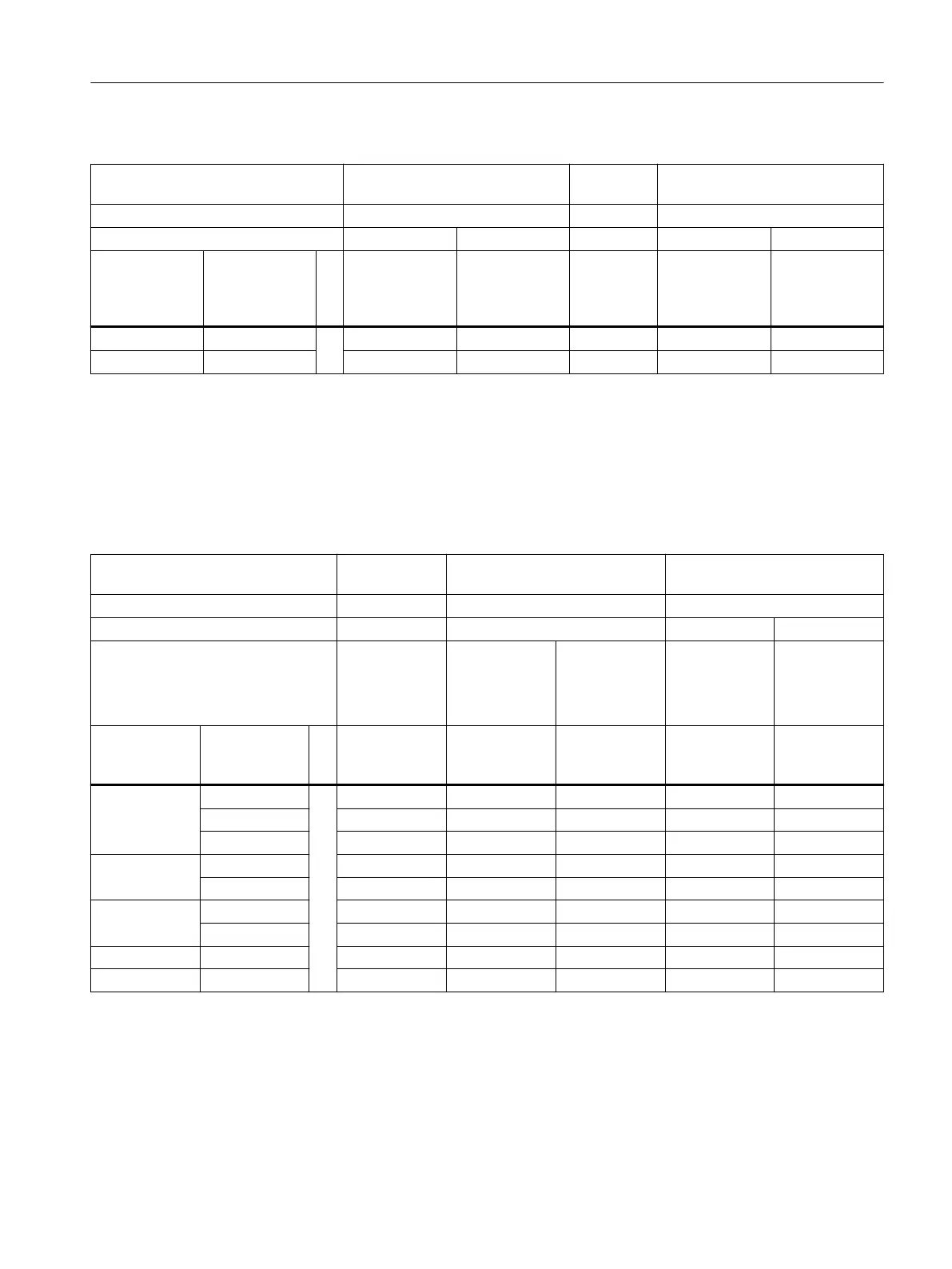
Table 11-6 Type 2N
Header type BA0: BB0; BC0; BD0; AA0, AB0,
AC0, KJ0, BS0, AG0
BMO, BT0,
AH0
BP0
T
max
Header 100 °C 80 °C 100 °C
Temperature class T4 T6 T6 T4 T6
Temperature
of medium (°C)
Temperature
rise caused by
medium ΔT2G
(K)
T
2
in °C T
2
in °C T
2
in °C T
2
in °C T
2
in °C
100 °C 7 100 73 73 100 73
80 °C 5 100 80 80 100 80
Gas hazardous area: Ex d / XP
The maximum ambient temperatures T
a
for the respective connection head with or without
transmitter can be obtained from the cells in the following tables. The temperature increase
given by the medium is already considered there.
Table 11-7 Gas Ex d
Head type AH0, AV0, SI‐
TRANS TF
AG0, UG0 AU0, UU0
T
max
head 85 °C 100 °C 120 °C
Temperature class T6 T4 T3 T4
Max. permitted power consump‐
tion of electronic (W)
0 ... 3
1)
With or with‐
out electronic
0
Without elec‐
tronic
1 ... 3
1)
With electron‐
ic
0
Without elec‐
tronic
1 ... 3
1)
With electron‐
ic
Medium tem‐
perature (°C)
Extension
length "X"
(mm)
T
a_max
in °C T
a_max
in °C T
a_max
in °C T
a_max
in °C T
a_max
in °C
440 °C 40 43 76 53 96 48
80 55 88 65 108 60
150 ... 300 61 94 71 114 66
290 °C 40 54 87 64 107 59
80 ... 300 61 94 71 114 66
200 °C 40 58 91 68 111 63
80 ... 300 63 96 73 116 68
130 °C 40 ... 300 61 94 71 114 66
80 °C 40 ... 300 67 100 77 120 72
1)
For the determination of ambient temperatures, maximum enclosure temperature of 85 °C was taken as a basis when
electronic are incorporated.
Technical data
11.1 Rated conditions
SITRANS TS100/TS200/TS300/TS500/TSinsert/TSthermowell
Operating Instructions, 08/2020, A5E47810090-AA 135