Hydro:Evolved User Manual
Page 96 © 2022 Smartrise Engineering, Inc. All Rights Reserved October 2022
Proceed on inspection up and down the hoistway and adjust each tape guide clip to the correct
in-line position with respect to the Sensor Array Assembly.
The camera powers up when the CT station is powered up.
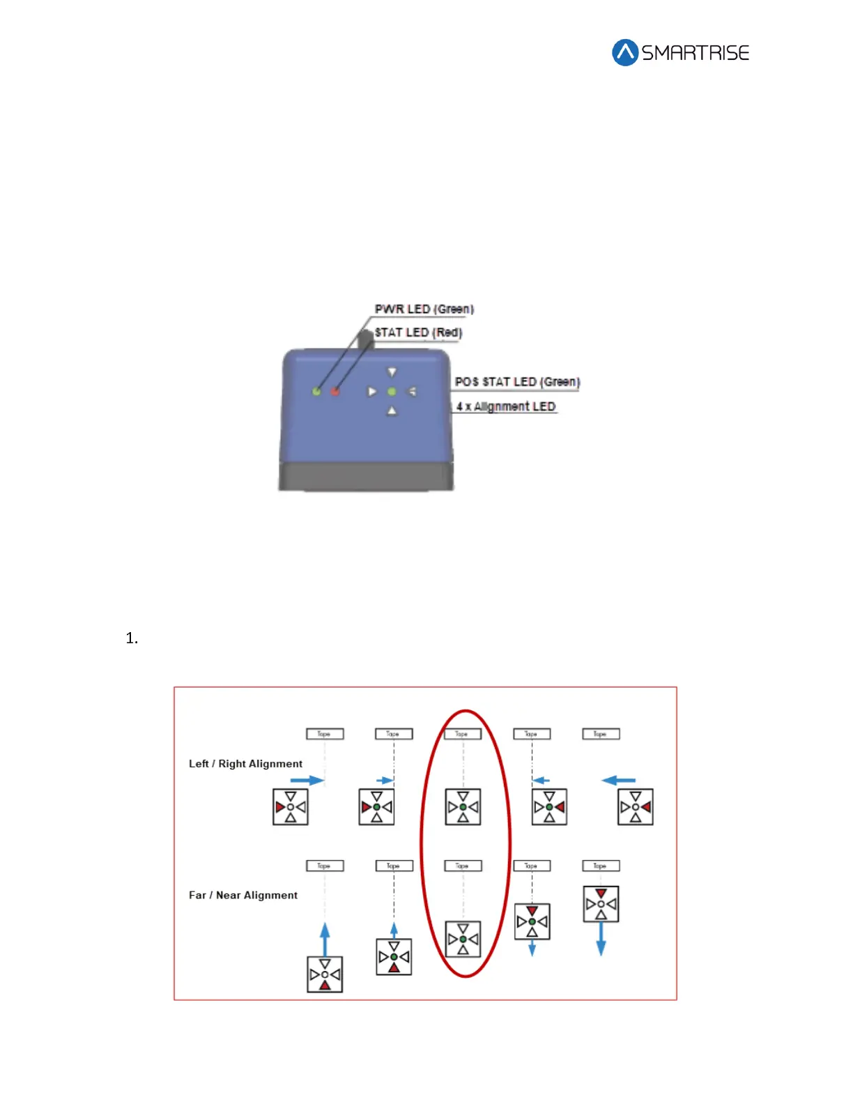
9.9 Alignment
Alignment and Position Status LEDs are located on top of the optical sensor. These LEDs are
used to align the sensor to the tape.
Figure 111: Optical Sensor LEDs
When the optical sensor needs to be aligned, the red arrow LEDs indicate which way to move
the sensor.
The following procedure describes how to align the optical sensor.
Loosen the two mounting bolts on sensor base plate or sensor bracket to adjust the
sensor position, as required.
Figure 112: Alignment Arrows