Hydro:Evolved User Manual
October 2022 ©2022 Smartrise Engineering, Inc. All Rights Reserved Page 19
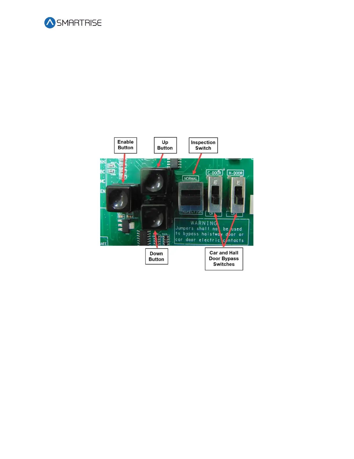
INSPECTION Switch – Toggles between inspection and normal operation. When the MM input
signal is high and the switch is set to INSPECTION, the system is in Construction Mode. If the
switch is set to NORMAL, the system is in test mode.
UP and DOWN Buttons – Moves the car either up or down on Inspection and Construction
Mode.
CAR and HALL DOOR BYPASS Switches – Bypasses the hall locks and Gate switch (GSW) only on
CT and IC inspection. These switches are used instead of jumpers to reduce the risk of
accidentally leaving a jumper still connected. These switches are not used in Construction Mode
and the controller faults out if used any time outside CT or IC inspection.
Figure 22: MR Board SR3032 Inspection Control
2.1.13 Safety Relays
SFM – The force guided relay that is controlled by the main processor. The status of the relay is
monitored by both the main processor and the safety processor. When the relay is active,
contacts that are in series with SFP output voltage to the SAFE terminal are used to control the
valves.
SFP – The force guided relay that is controlled by the safety processor. The status of the relay is
monitored by both the main processor and the safety processor. When the relay is active,
contacts that are in series with SFM output voltage to the SAFE terminal are used to control the
valves.
EB1 – The force guided relay that is controlled by the safety processor. The status of the relay is
monitored by both the main processor and the safety processor. When the relay is active,
contacts that are in series with EB2 pass through voltage from the EBS terminal to the EB
terminal.