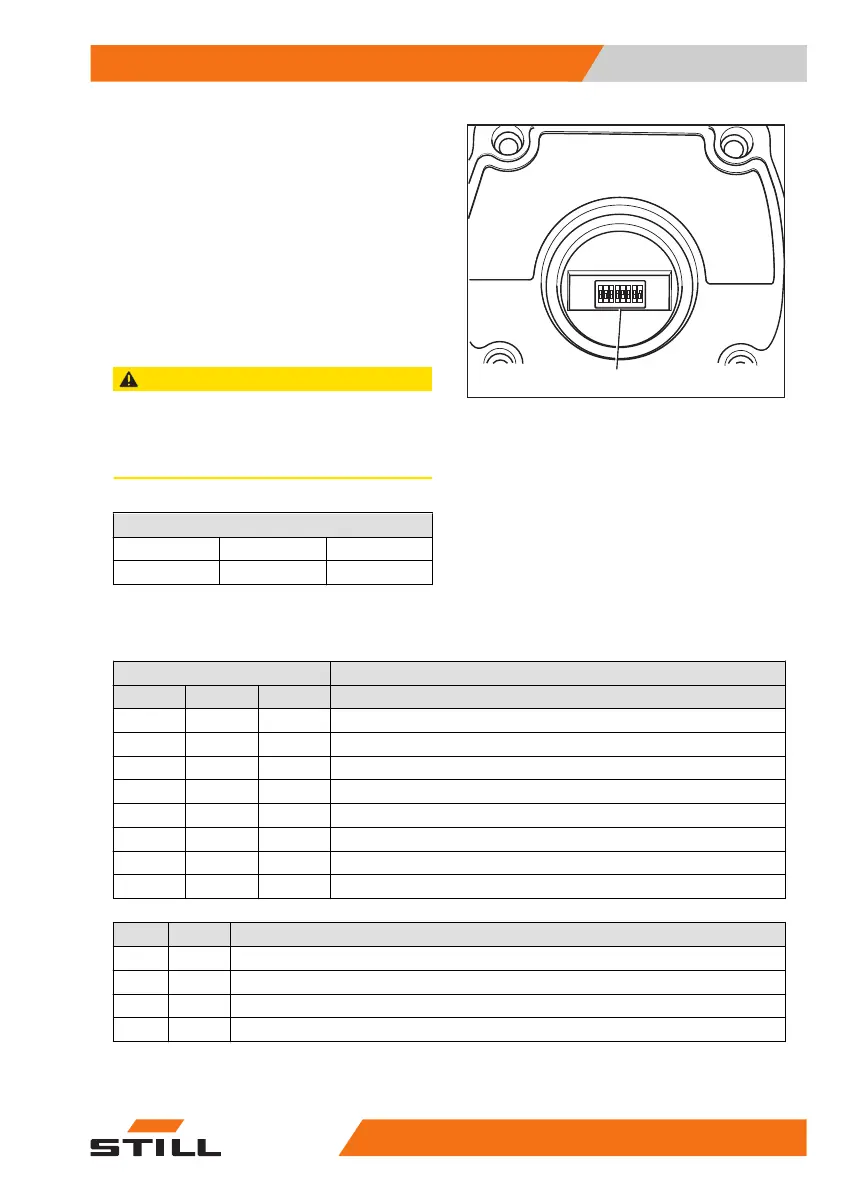
The sensor is adjusted using DIP switches (6).
– To access the DIP switches, open the cover
on the underside of the sensor housing with
the key (5).
During this process, the two tabs of the key (5)
fit into the recesses of the cover.
– Using the DIP switches "1 to 5" (6), adjust
the range and the sensitivity of the sensor.
The DIP switches can be adjusted using a
small screwdriver.
CAUTION
The settings for DIP switches "6 to 8" are the factory
settings of the manufacturer.
Do
not
change the factory settings of the manufac-
turer!
Factory settings of the manufacturer
DIP switch
678
110
The possible settings for DIP switches "1 to 5"
are shown in the following tables:
DIP switch
1 2 3 Range
000 2 m
001 3 m
010 4 m
011 6 m
100 8 m
101 12 m
110 16 m
111 24 m
4 5 Sensitivity
00 Very high
01 High
10 Medium
11 Low
12345678
6
DIP-Schalter_V2
Operation
4
Auxiliary equipment
33956368011531 EN - 01/2021 - 05



 To Next Page