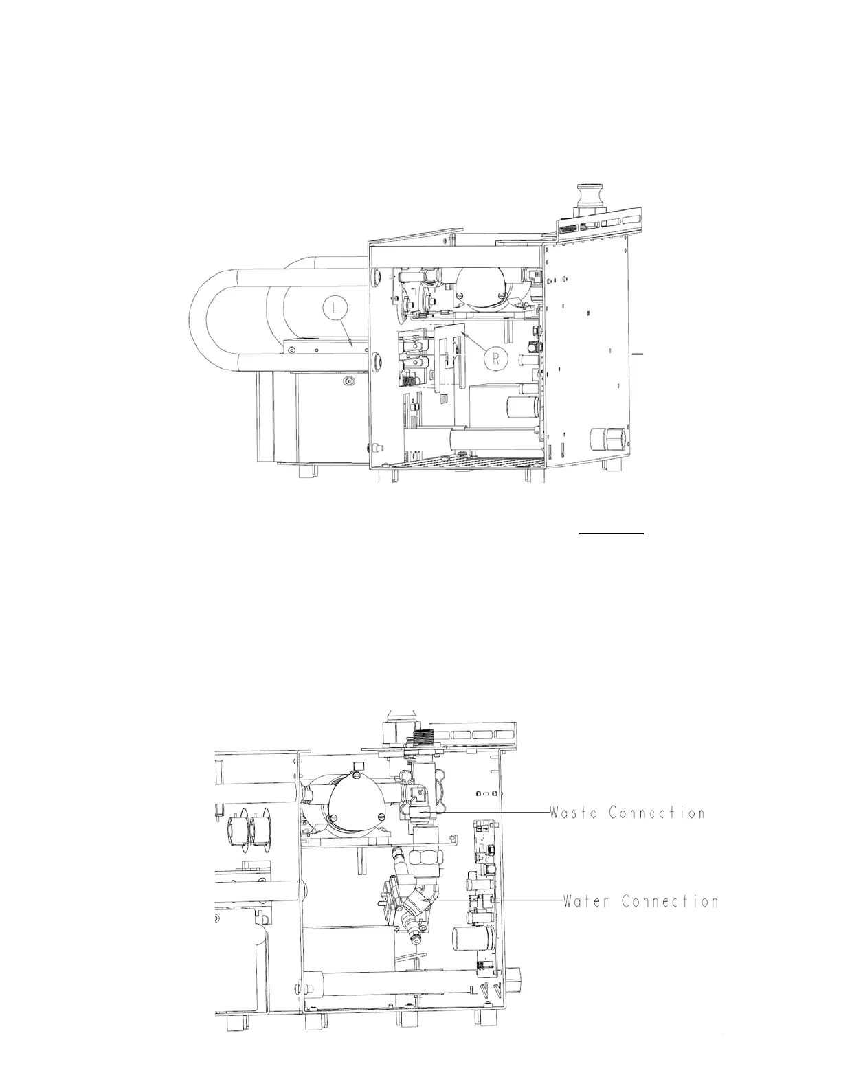
5. Push actuator cover (P/N 0702-014-012) (L) inside chassis enough to remove
actuator cover back (P/N 0702-014-014) (R). Continue to push actuator cover (P/N
0702-014-012) (L) back to remove.
6. Unplug the connector from docker power coupler assembly (P/N 0702-014-114) at J1
of the docker power coupler PCBA (P/N 0702-014-510) (H). Carefully cut all wire ties
used to secure this cable.
7. Unplug the connector from stepper motor assembly (P/N 0702-014-123) at the point
where it connects to the docker main wire harness (P/N 0702-014-021).
8. Disconnect three connectors from hall sensor wire harness (P/N 0702-014-021F).
Each connector is different to prevent from reinstalling incorrectly.
9. Using an adjustable wrench, disconnect coupling offload hose (P/N 0702-014-129)
(D) at the connection to the offload pump (P/N 0702-014-201). Next, remove the
coupling inlet hose (P/N 0702-014-128) (C) at the connection to the water inlet
assembly (P/N 0702-014-400) (AF)
4-4
 Loading...


