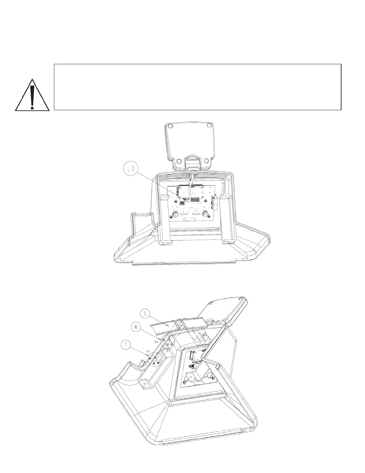
8. Disconnect the cable from the volume display assembly connected to J3 on main
control board.
Note: The wire harness connected to J3 is shown here in a previous configuration. The
new installation method secures the harness with a cable tie that must be cut when
removing the connector. If the wire harness is in the new configuration, be careful not to
cut the wire harness when removing the cable tie. Always be sure to replace the cable
tie when reinstalling the connector.
9. Remove four socket head cap screws (P/N 0004-523-000) (T), four flat washers (P/N
0011-491-000) (W), and stiffener (P/N 0702-001-856) (S) and set aside.
2-23
 Loading...


