3.5 Operation Procedure (Measurement/Measurement2)
51
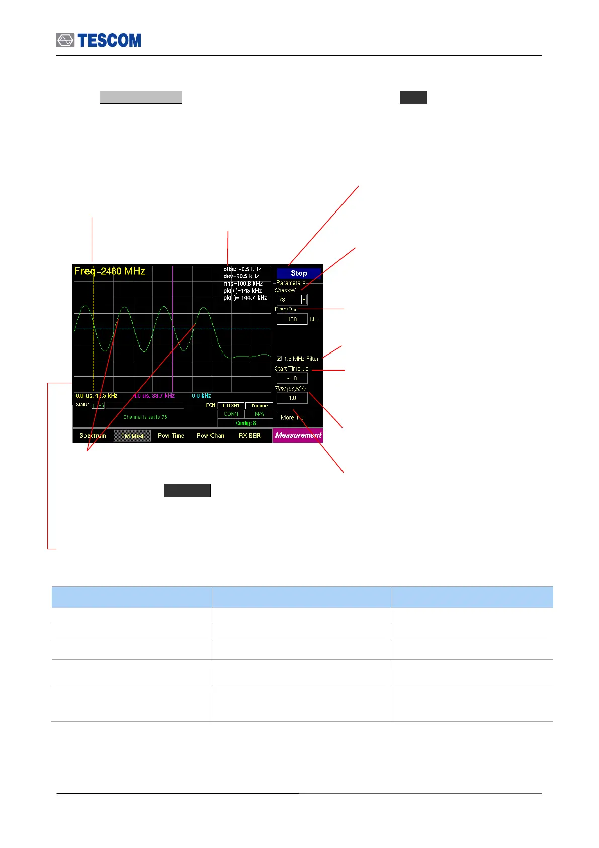
2. FM Modulation: To access FM Modulation screen, press M2 soft key. This screen
shows the modulation characteristics of a channel in single channel or hopping mode.
0.1~ 180 @ 3 slots packet
0.1 ~ 300 @ 5 slots packet
Center Frequency:
Displays channel
frequency.
Channel: Select the carrier frequency
channel, one of 79 channels or Hopping
mode. (Channel 0-78: 2.402 – 2.480 GHz)
1.3 MHz Filter: Enables 1.3 MHz Low Pass
Filter
Line Markers: You can place line-shaped markers on the
screen to find the signal’s frequency and time. To activate
a maker, press the Marker key in sequence. An
activated marker changes to a solid line. Turn the knob to
place the marker at the signal.
Readouts of markers time and frequency: The marker
readouts have the same color as the marker respectively.
Test mode: Configures Bluetooth Test Mode
connection with DUT
Time (us)/div: Sets the horizontal time per
division
Start Time: Specifies the start point to display the
measured signals. “0” means the start point of a
slot time (625 uS).
All following values are measured between yellow and blue marker.
offset: Carrier Frequency offset
dev: Average of absolute deviation values
rms: RMS value of deviation
pk(+): Positive maximum deviation
pk(-): Negative maximum deviation
Start/Stop: When this menu is pressed the
tests will run once. When pressed again
while the tests are running, the testing will
stop.
Freq/Div: frequency value of one vertical grid
on screen