iCNC Performance
7-4 iCNC SETUP Manual 0-5401
When the controller reboots, you will be prompted to transfer the newly modified ROBOPRM1.DAT file to the background
CPU. Select YES and give the password to complete this action. When completed, restart iCNC Setup as explained above.
7.3.2 Drive and Encoder Polarities Step/Dir
• Make sure the Drive Enable on the front of the controller is “OFF”
• Make sure that power is ON to the servo amplifier system and that clutches (if any) are engaged on two axis systems.
Remember to keep the Y1 and Y2 pinions out of the rack in three axis systems. In certain applications, you have to
set the optical tracing system to the trace state to enable driving simultaneously in both directions.
• Make sure that the controller is in basic status (no lights-on any of the push buttons are illuminated on the front panel.)
Put the Drive Enable Switch on the front of the controller to “ON”
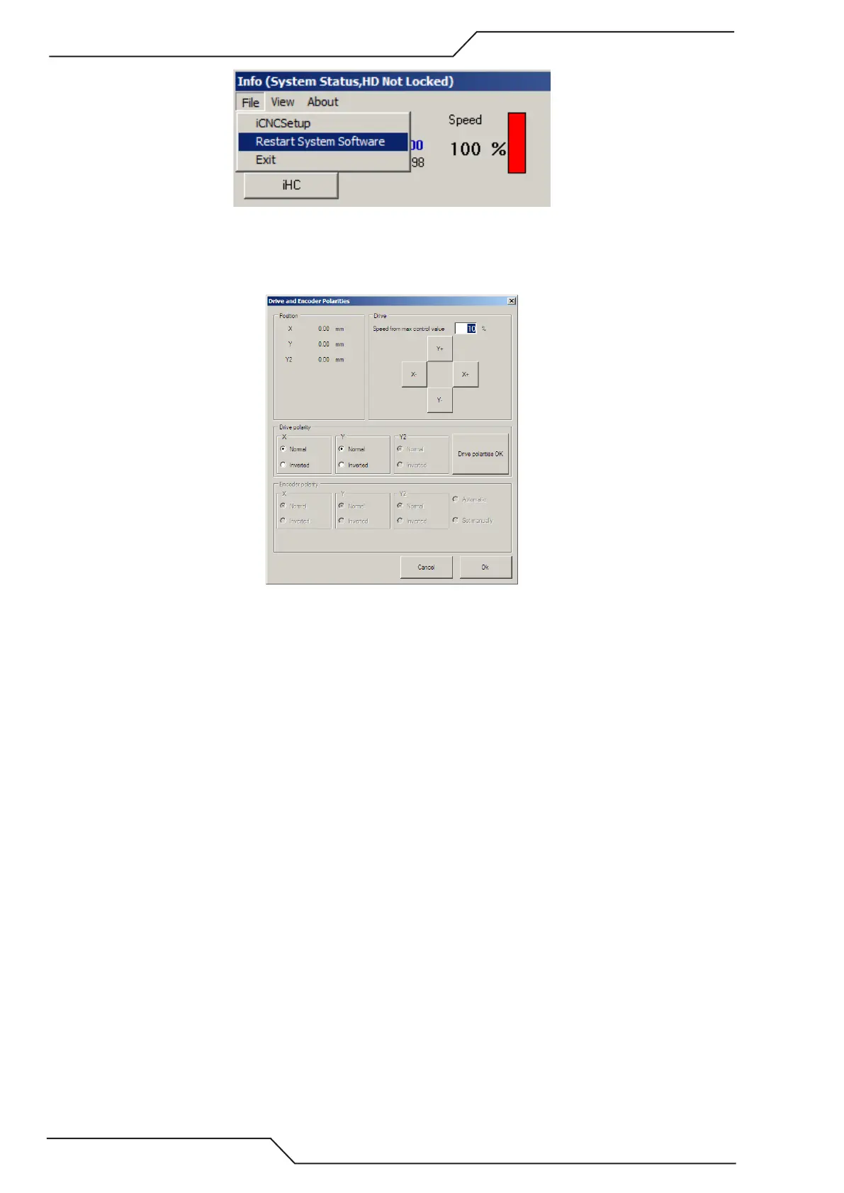
Opening this dialog box opens the positioning loop and allows you to send out speed signals to the drives by using Y+/Y-/
X+/X- buttons and checks the actual rotation of the drive pinion wheels. If rotation is incorrect, change the corresponding
polarity in the dialog box and check again.
After all polarities are correct, click the Drive Polarity OK check box.
Next, set the encoder polarity by pressing the Y+ direction for about 2 seconds. If the polarity is incorrect, the software
will automatically detect it and change the setting automatically. Repeat for the +X direction. Click OK when completed.
After you are done put the drive enable back to OFF.