iCNC Performance
Manual 0-5401 iCNC SETUP 7-13
After the test speeds appear, select Calculate low speed corrections. With optimum drives and perfect adjustment, all the
correction values will come in at 1. Press the ZERO push button on the controller, then select OK when ready.
If you are using an old machine with poor response servo amplifiers and the machine won’t move with the default set-
tings, you can adjust the minimum speed with Increase and Decrease buttons until the motors actually start to move.
Put the Drive Enable Switch on the front of the controller to “OFF”.
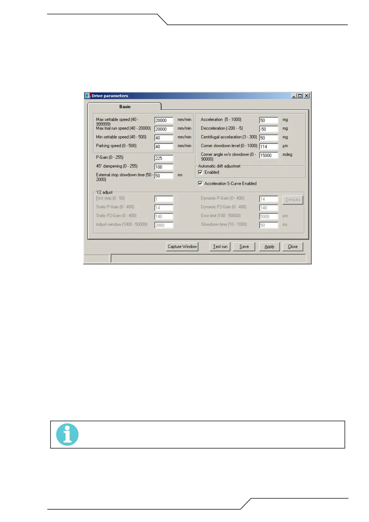
7.4.8 Motion Parameters
• Max settable speed is the maximum desired machine speed. This can be the same as set in Max Speed Test, or maxi-
mum machine speed can be limited.
• Max trial run speed is normally set equal to the Max settable speed.
• Min settable speed is set to your lowest dependable speed. The system enters this value in automatically after complet-
ing the Min speed test.
• Parking speed is used for max machine positioning and drift correction, either while the machine is standing still, or
positioning to a part location. Small values will make it impossible to properly position the machine.
• P-Gain (0 – 255) A critical gain setting controlling system responsiveness and performance. If the encoders are driven
directly off the motor shafts, a value of 190-210 works well in most cases. If the encoders are separately mounted and
measure off the machine carriage, this value may need to be dropped as low as 75.
• 45° dampening can be increased from the default value of 100 if vibration is seen, especially when driving at a 45°
angle.
• External stop slowdown time controls the reaction time between when an external stop input is received, and when
the controller halts motion.
• Acceleration and Deceleration controls the Acc/Dec responsiveness when positioning the machine. With fast plasma
machines, a value of 35-50 mg is normal. If the machine is mechanically very rigid, with near zero backslash and a
strong drive system, you might be able to use values as high as over 100 mg. For slow gas cutting machines, a value
of 15 mg is normal. Both acceleration and deceleration values are generally adjusted equally.
NOTE!
One G (the value describing how fast an object accelerates when dropped to a free fall on earth) is 9.81 m/s/s. Therefore 10
mg (milli-g) is 0.0981 m/s/s or 9.81 cm/s/s.
• Centrifugal acceleration will limit the maximum speed of the machine when driving on small radius arcs or approach-
ing sharp corners. This must be set to a value equal-to or less than your acceleration or deceleration values, and can
be set as low as 3 mg.
• Corner slowdown level value for sharp corners. Affects the allowed speed for sharp corners, too low value will cut
away the part to be cut, too high value will make rounder corners.