iCNC Performance
7-40 iCNC SETUP Manual 0-5401
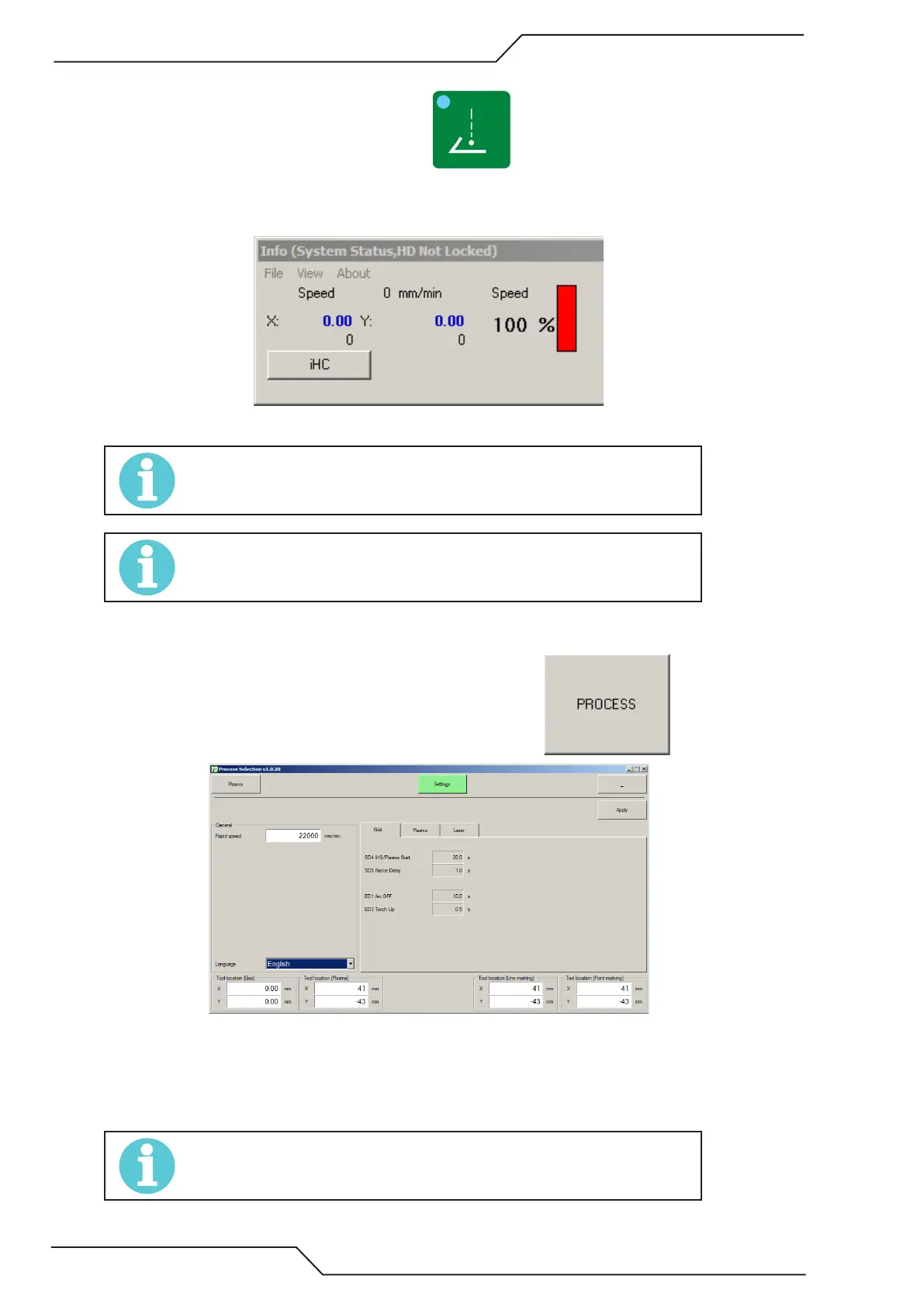
7. Double check that the position counters are zero.
8. Turn ON the pointer device. Normally activated by the button.
9. Now manually jog the machine so that the pointer device is in the center of the pierced hole.
10. Check the coordinates from the Info screen. These coordinates will show the tool offset value.
NOTE!
Make sure to note the possible - sign in the coordinate as this will have an aect how the
distance is measured.
NOTE!
Default tool oset using Thermal Dynamics lifter is ~X-axis 41mm [1.614”] / Y-axis -43mm
[-1.693”]
8.2 Setting the tool offset values
1. You can set the tool offsets in the process selection settings page. Click and select settings.
2. Key in the appropriate values.
3. Click Apply in the settings screen.
4. Go and apply a cutting process (example click the Plasma button that opens your cut process selection screen, select
a process and click apply) and the tool offset will be updated.
NOTE!
Copy the plasma tool oset to line and point marking osets If plasma is used as a marking
device as well.