iCNC Perfromance
Manual 0-5401 APPENDIX B B-13
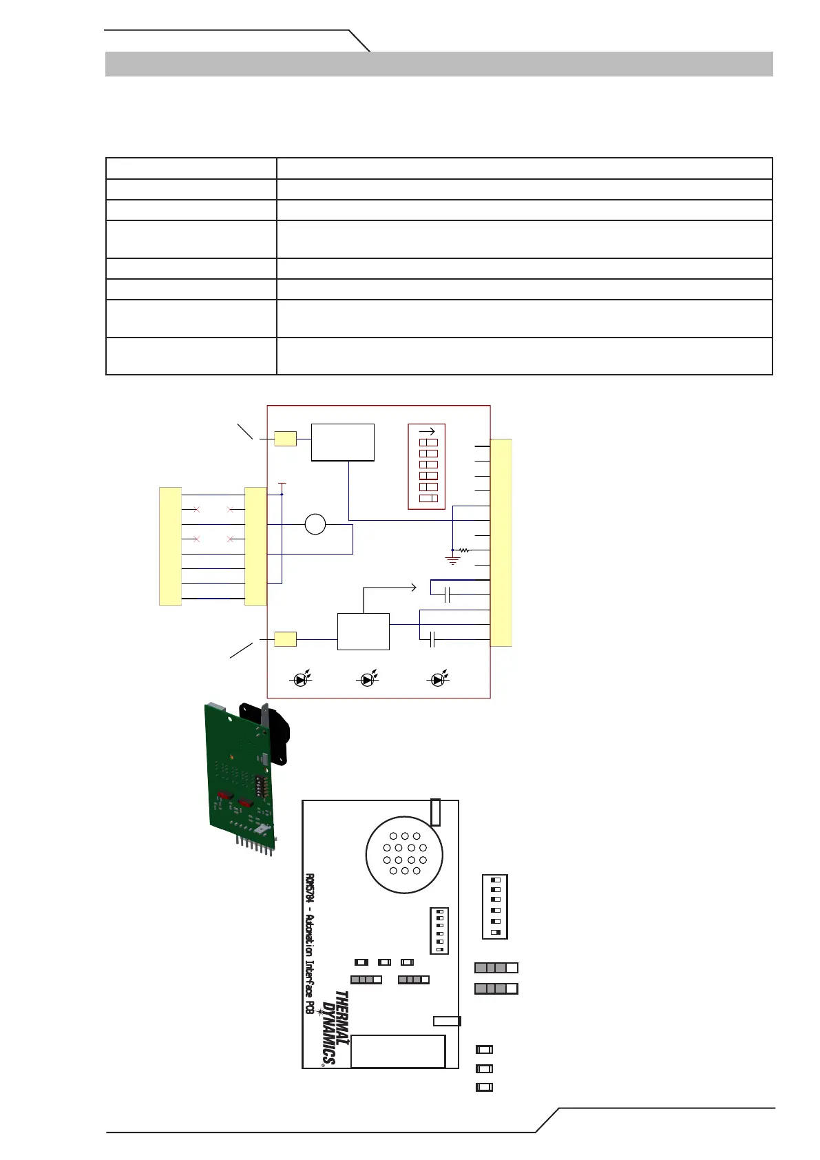
B.3 Thermal Dynamics A-Series Automation PCB
The Automation Interface PCB provides ohmic sensing (separate cable to ohmic clip), tip sensing (exposed consumables),
multiple arc voltage divisions and plasma I/O signals to the CNC.
Connections:
Contact rating 30VAC/VDC, 1 A max.
Minimum signals required Start / Stop and OK to Move.
Arc Voltage Selection (DIV1) Only 1 dip switch can be active at a time, measuring range 250V.
Arc Voltage Polarity Isolated from plasma power supply ground, change polarity by swapping wires on SIG
(J1-6) and COM (J1-5) Either pin can be grounded.
Arc Voltage Output Isolated from plasma power supply ground, both signal and com needs to be connected!
Ohmic Sensing With wire connected to J1-13 from shield cup.
Tip Sensing for Ign. Height If switch SW2 is ON Tip Sensing will trigger Plate Contact out when tip comes to contact
with Work. This only works with exposed parts.
Tip Sensing During Cutting If switch SW3 is ON tip sensing will trigger plate contact out when tip comes to contatc
with work while cutting. This only works with exposed parts.
1
2
3
4
5
6
7
8
9
10
11
12
13
14
J1
1
2
3
4
5
6
7
8
*
J2
OK TO MOVE
GND
+12V
OK TO MOVE
1
-V_0UT1
1
TIP
1
2
3
4
5
6
7
8
P10
START / STOP
CONTACT
M-ARC
START
123456
DIV1
CONTACT
Ohmic
sensing
circuits
To TIP1
MAIN PCB
(PCB1)
Start / Stop (COM), dry contact to #4 will re the arc
Start / Stop, dry contact to #3 will re the arc
Divided Arc voltage out (COM)
Divided Arc voltage out (SIG)
COMMON
Plate contact (COM)
Plate contact (OUT)
OK to Move (COM)
OK to Move (OUT)
Ohmic input from shield cup
To -V OUT 1
Main PCB
( PCB1)
Voltage
Divider
Signals
1
I 0 I
0
2 3 4 5 6
ON
1 2 3 4 5 6
ON
I 0
I
0
Div 1
Div 1
Divider ratio:
1 ON rest OFF 16.67:1 (SC11)
2 ON rest OFF 20:1 (ESAB)
3 ON rest OFF 30:1
4 ON rest OFF 40:1(INOVA)
5 ON rest OFF 50:1(IHT, SC3000, Hypertherm)
6 ON rest OFF 80:1(iHC, iCNC Performance)
Switches:
SW2 = Tip sensing ON
SW3 = Tip sensing during cutting ON
LEDs:
Contact, red: Plate contact active when illuminated
Connector -V0_1:
Wire to plasma MAIN PCB (PCB1)
Connector TIP:
Wire to plasma main board
Connector J2:
Cable to J10 on plasma MAIN PCB (PCB1)
M-Arc, green: Main arc output ON when illuminated
Start, yellow: Plasma Start input ON when illuminated
SW2
SW3
CONTACT M-ARC START
SW3SW2
CONTACT
M-ARC
START
1 3
1412
J1
TIP
-V_OUT1
J2