iCNC Performance
4-2 MOTION Manual 0-5401
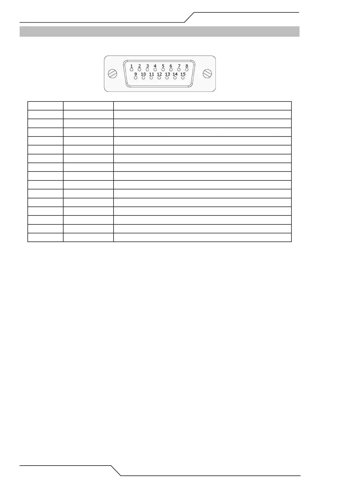
4.2 J47 Servo Connector
4.2.1 Servo Pin arrangement
Pin number Name Description
1 X-Axis Direction + Differential Direction signal for X-Axis. 5V logic
2 X-Axis Step + Differential Step signal for X-Axis. 5V logic
3 Y-Axis Direction + Differential Direction signal Y-Axis. 5V logic.
4 Y-Axis Step + Differential Step signal for Y-Axis. 5V logic
5 X-Axis Speed +/- 10VDC analog speed signal for X-Axis.
6 Y2-Axis Speed +/- 10VDC analog speed signal for Y2-Axis.
7 5VDC 5VDC Output max current 1A
8 GND Signal GND
9 X-Axis Direction - Differential Direction complement for X-Axis. 5V logic
10 X-Axis Step - Differential Step complement for X-Axis. 5V logic
11 Y-Axis Direction - Differential Direction complement for Y-Axis. 5V logic
12 Y-Axis Step - Differential Step complement for Y-Axis. 5V logic
13 Y-Axis Speed +/- 10VDC analog speed signal for Y-Axis.
14 Servo Enable Servo enable signal, active LOW
15 GND Signal GND