iCNC Perfromance
Manual 0-5401 APPENDIX B B-5
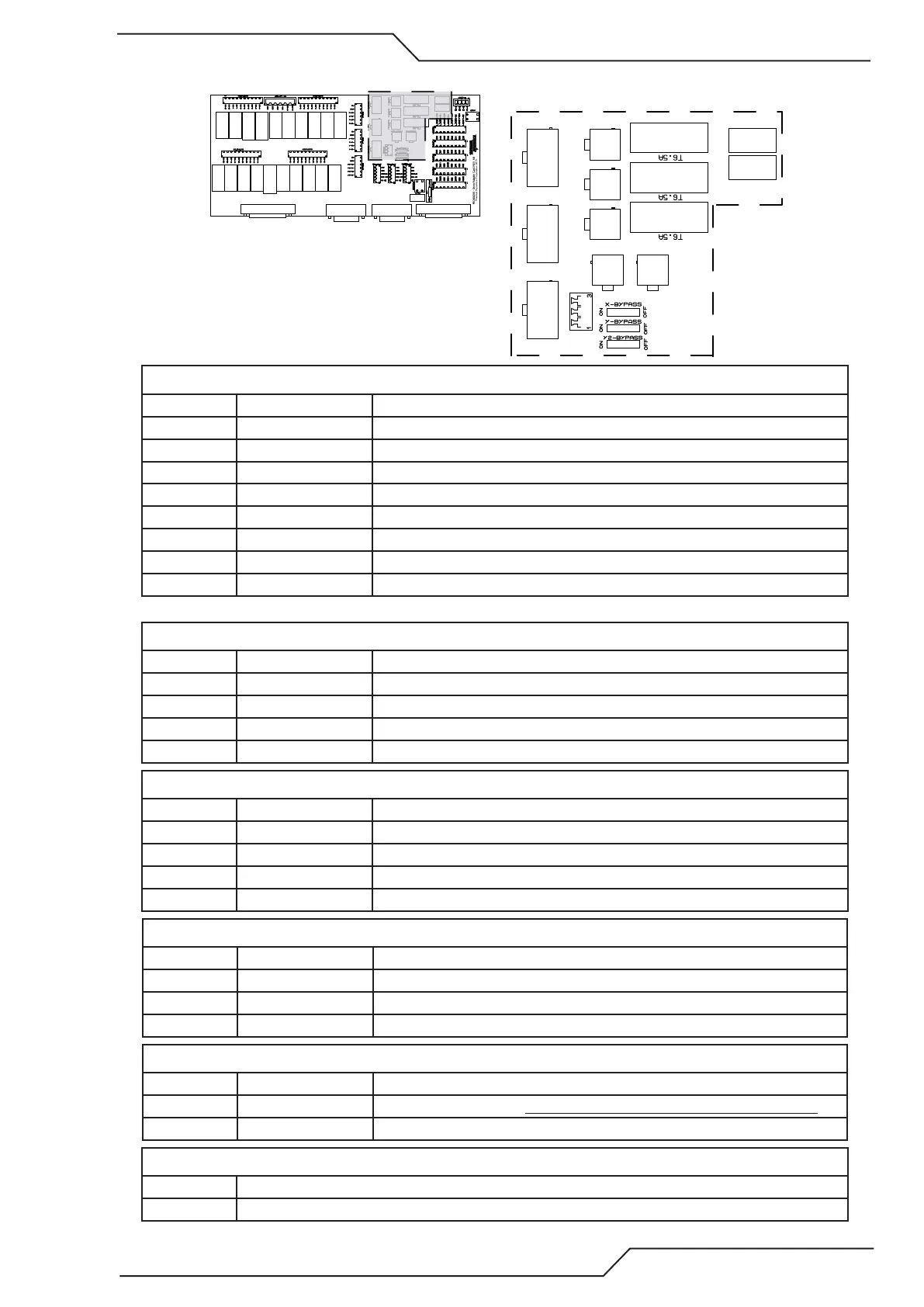
B.1.6 Teknic Connectors
INPUTSSERVOENCODEROUTPUTS
X-CTRLY-CTRLY2-CTRL
SHIELD
POWER IN POWER IN
X-POWERY-POWER
Y2-POWER
Connectors CTRL X/Y/Y2, mating connector Molex P/N 39-01-2080
Pin number Name Description
1 Output + Servo OK + signal, 5V logic
2 Input B+ Step + signal, 5V logic
3 Input A+ Direction + signal, 5V logic
4 Enable + Enable signal +, 5V logic
5 Output - Servo OK + signal, 5V logic
6 Input B- Step - signal, 5V logic
7 Input A- Direction - signal, 5V logic
8 Enable - Enable signal -, 5V logic
Servo error hardwired to inbit15.
Connectors Power X/Y/Y2, mating connector Molex P/N 39-01-2040
Pin number Name Description
1 V+ Teknic motor 75VDC output
2 GND Teknic motor GND output
3 V+ Teknic motor 75VDC output
4 GND Teknic motor GND output
Connectors Power in, mating connector Molex P/N 39-01-2080
Pin number Name Description
1 V+ Teknic power supply 75VDC Input
2 GND Teknic power supply GND Input
3 V+ Teknic power supply 75VDC Input
4 GND Teknic power supply GND Input
Connector Shield, mating connector Wurth P/N 691361100003
Pin number Name Description
1 Shield Cable shield
2 Shield Cable shield
3 Shiled Cable shield
Switches X/Y/Y2 Bypass
Pin number Name Description
1 ON Teknic Servo OK disabled. Needs to be set to ON if there is no motor connected.
2 OFF Teknic Servo OK signal enabled.
Fuses, Littelfuse P/N 021806.3
Name Description
T6.5A 5x20mm 6.3A slow blow