iCNC Perfromance
Manual 0-5401 INPUT POWER 5-1
SECTION 5: INPUT POWER
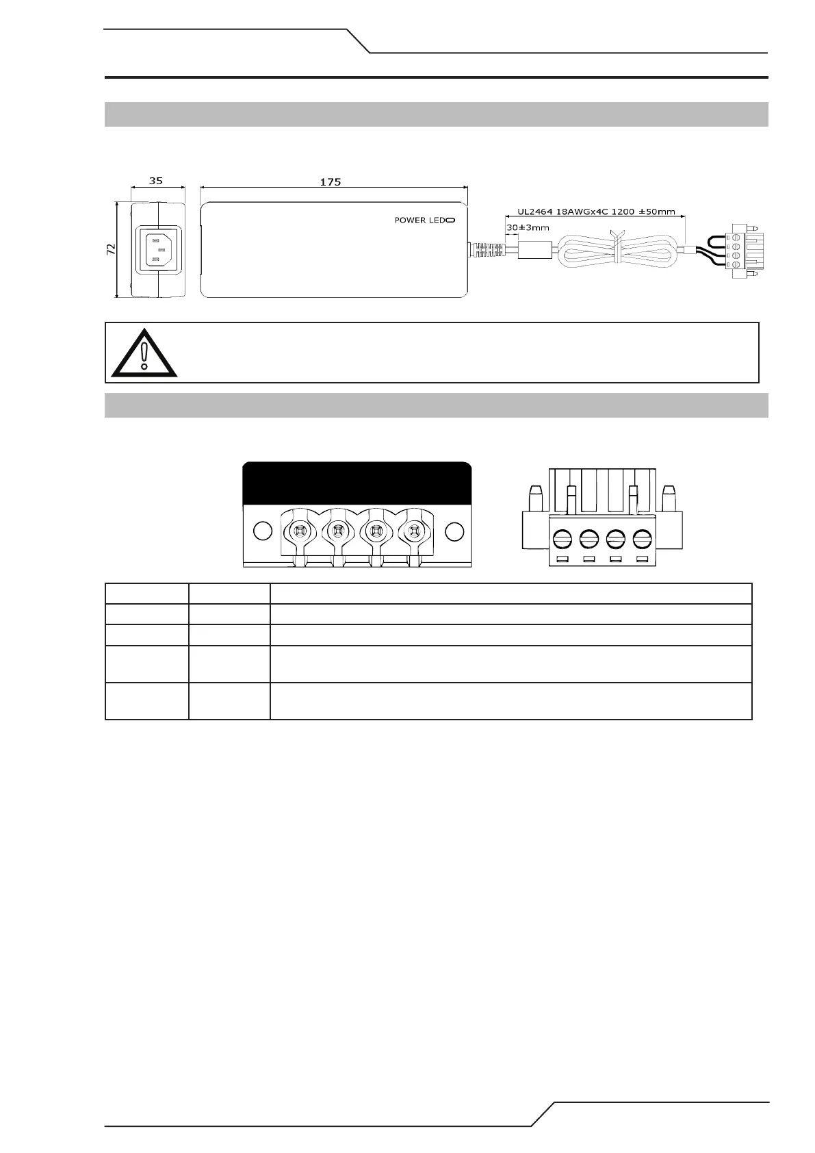
5.1 Power Supply
iCNC Performance comes with an optional 24VDC 6.67A power supply. The connector for the main power for the iCNC is an
IEC C13, that should be rated for 10A 250V.
!
CAUTION
Wire sizes are for reference only. The installation must conform to national and local codes for the type and method of wire
being used.
5.2 Power Connector
5.2.1 Power Connector Pin Arrangement
i
GND 24VDC E1 E2
Pin number Name Description
1 GND Power input GND
2 24VDC Power input +24VDC
3 E1
External Stop input signal. Provide a dry closing contact to pin #4 to enable I/O and
motion outputs.
4 E2
External Stop input signal. Provide a dry closing contact to pin #3 to enable I/O and
motion outputs.