iCNC Performance
6-8 iHC Manual 0-5401
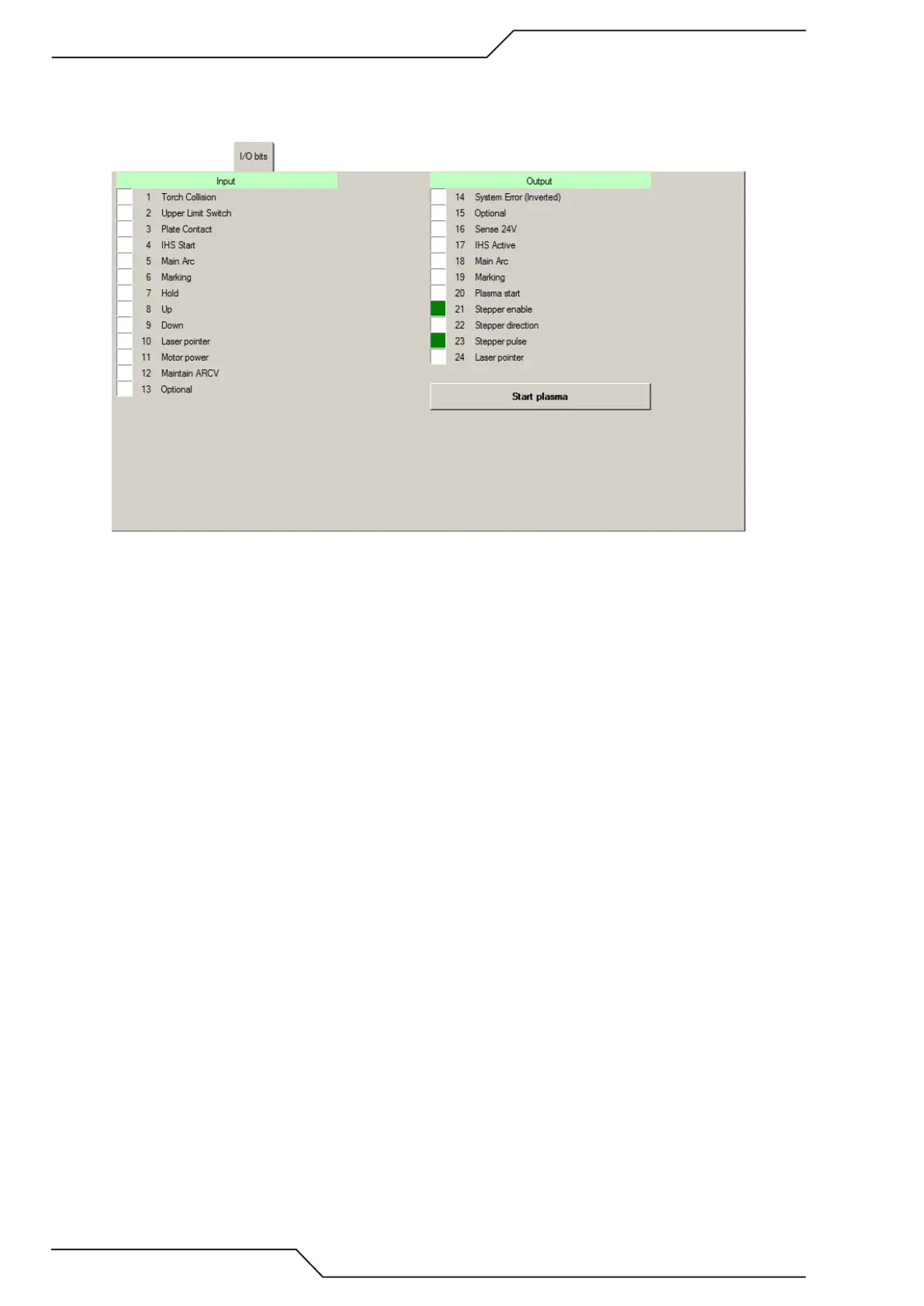
6.7.2 IO Bits Tab
This tab displays the status of various system signals for diagnostic purposes. I/O bits are separated to inputs (signals that
come from other devices to iHC) and outputs (signals that go from the iHC to iCNC Performance).
Inputs
1. Torch Collision In case the lifter has a breakaway/collision sensor, signals from the sensor can be wired into Torch
Collision input. Torch Collision will activate System Error output to CNC
2. Upper Limit Switch Used to find home position when iHC is turned on
3. Plate Contact Inbit becomes active on plate contact during IHS or cutting sequence.
4. IHS Start Inbit from CNC becomes active when the IHS sequence starts.
5. Main Arc Inbit from plasma which indicates plasma arc has ignited.
6. Marking Inbit to put height controller to marking mode.
7. Hold AVC turns off when Hold inbit turns active. Hold is used during cutting to prevent the torch from diving into the
plate when movement slows down ie: during tight corners.
8. Up Inbit from CNC that moves the torch up.
9. Down Inbit from CNC that moves the torch down.
10. Laser pointer Inbit from CNC to turn on the laser pointer output
11. Motor power Inbit telling is the motor power turned ON.
12. Maintain ARCV Reserved for future use.
13. Optional Reserved for future use.