EasyManuals Logo

Thermal Dynamics iCNC Performance User Manual

Thermal Dynamics iCNC Performance
138 pages
To Next Page IconTo Next Page
To Previous Page IconTo Previous Page
Page #44 background imageLoading...
Page #44 background image
iCNC Performance
6-2 iHC Manual 0-5401
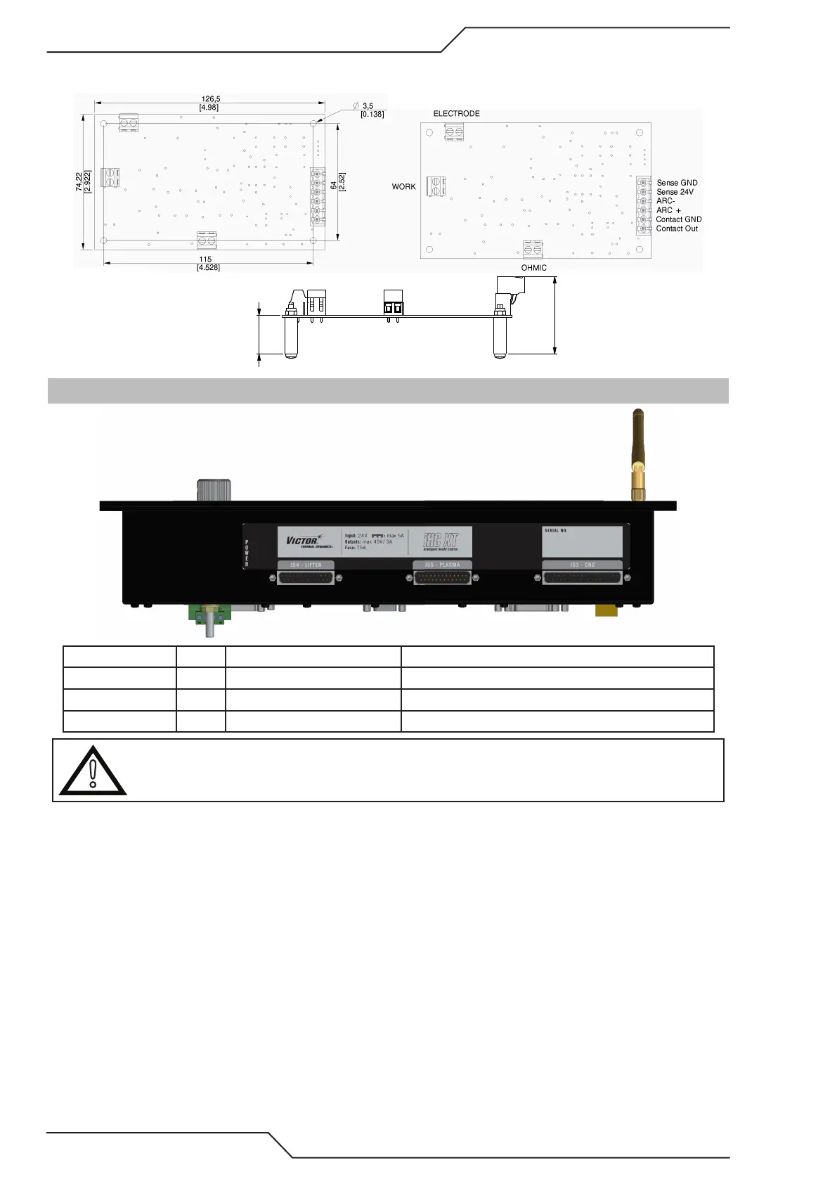
6.1.2 Voltage Divider Dimensions
Art # A-12561
Art # A-12560
21.50
[0.837]
42.50
[1.671]
6.2 Connector Locations
Picture reference ID Name Mating connector (example)
1 J54 Lifter 25pin male D-Sub Wurth 618 025 248 23
2 J55 Plasma 25pin female D-Sub Wurth 618 025 249 23
3 J53 CNC 37pin male D-Sub Wurth 618 037 248 23
!
CAUTION
When iHC is used with iCNC Performance all CNC to iHC signals are wired internally. Usually there is no need to connect
anything to J53 CNC connector.

Table of Contents

Questions and Answers:

Question and Answer IconNeed help?

Do you have a question about the Thermal Dynamics iCNC Performance and is the answer not in the manual?

Thermal Dynamics iCNC Performance Specifications

General IconGeneral
BrandThermal Dynamics
ModeliCNC Performance
CategoryController
LanguageEnglish