iCNC Perfromance
Manual 0-5401 APPENDIX B B-3
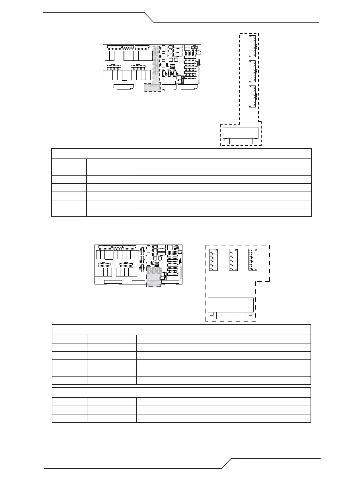
B.1.3 Encoder Connectors
ENCODER
5V
GND
Y2-A+
Y2-A-
Y2-B+
Y2-B-
5V
GND
Y-A+
Y-A-
Y-B+
Y-B-
5V
GND
X-A+
X-A-
X-B+
X-B-
INPUTSSERVOENCODEROUTPUTS
Connectors X/Y/Y2 ENC, mating connector Wurth P/N 691361300006
Pin number Name Description
1 5V 5VDC Output, max rating 1A
2 GND GND
3 A+ Differential encoder input, only 5V input
4 A- Differential encoder input, only 5V input
5 B+ Differential encoder input, only 5V input
6 B- Differential encoder input, only 5V input
Max input frequency 1Mhz, use shielded and twisted pair cables.
B.1.4 Servo Connectors
SERVO
SPEED-X
SPEED-Y
SPEED-Y2
EN
24V
GND
EN
EN COM
SPEEDX
24V
GND
EN
EN COM
SPEEDX
24V
GND
INPUTSSERVOENCODEROUTPUTS
Connectors Speed X/Y/Y2, mating connector Wurth P/N 691361100005
Pin number Name Description
1 EN Servo Enable NO Relay contact
2 EN COM Servo Enable COM
3 SPEEDX Analog Speed output +/- 10VDC
4 GND GND
5 24V 24VDC Output, max 1A
Connector Disable, screw on terminal
Pin number Name Description
1 NC/Disable Servo disable signal (inverted enable)
2 COM Servo disable com