iCNC Perfromance
Manual 0-5401 I/O 3-3
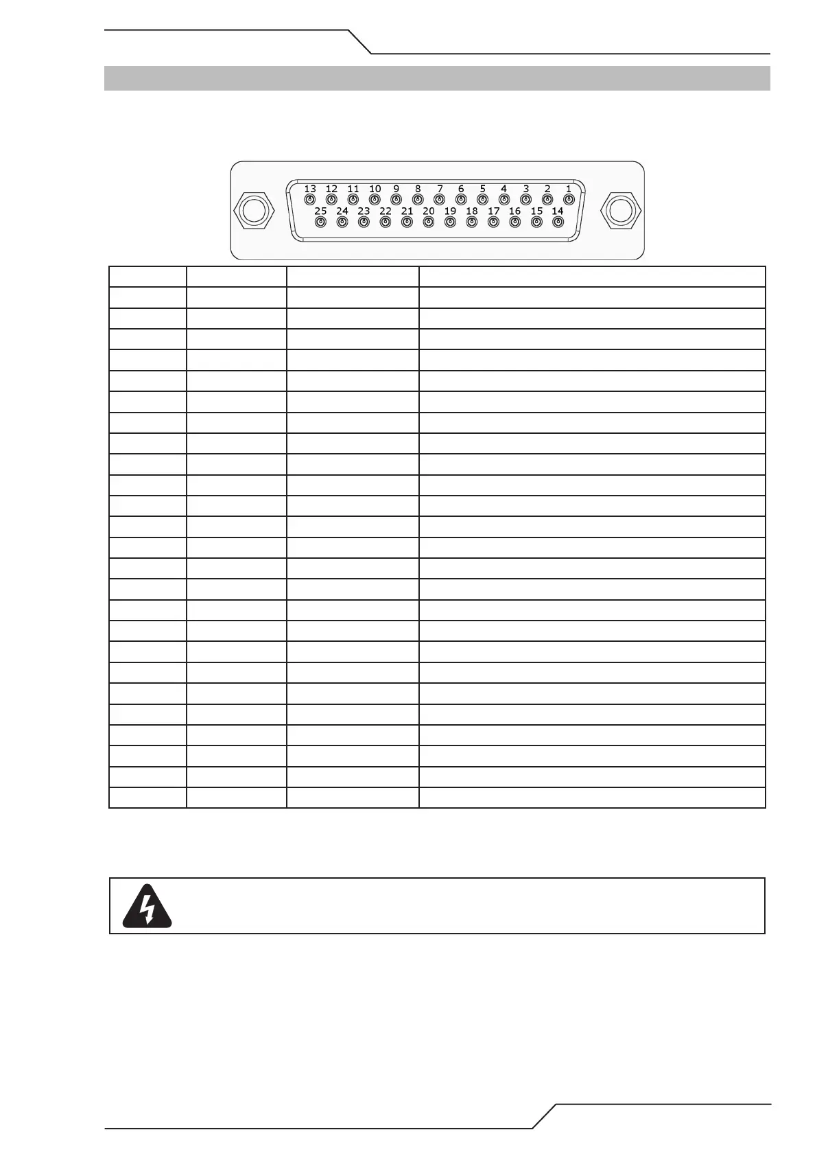
3.3 J46 Outputs
All outputs are active low. So the output pin will be low when active.
3.3.1 Output Pin Arrangement
Pin number Output number Default name Description
1 Outbit 0 Low PreHeat Output pin connected to GND when active
2 Outbit 2 Gas Torch Up Output pin connected to GND when active
3 Outbit 4 Ignition Output pin connected to GND when active
4 Outbit 6 Aux 1 Output pin connected to GND when active
5 Outbit 8 Aux 2 Output pin connected to GND when active
6 Outbit 10 Down Draft Output pin connected to GND when active
7** Outbit 12 Plasma Torch Up** Output pin connected to GND when active
8 Outbit 14 Auto Height Output pin connected to GND when active
9* Outbit 16 Aux 4* Output pin connected to GND when active
10 Outbit 18 Pointer Output pin connected to GND when active
11 24VDC Output 24VDC Output max combined current with pins #11/12/24 1A
12 24VDC Output 24VDC Output max combined current with pins #11/12/24 1A
13 GND Signal GND
14 Outbit 1 Cut Oxygen Output pin connected to GND when active
15 Outbit 3 Gas torch Down Output pin connected to GND when active
16 Outbit 5 Plasma Remote Output pin connected to GND when active
17 Outbit 7 High PreHeat Output pin connected to GND when active
18* Outbit 9 Corner Hold * Output pin connected to GND when active
19** Outbit 11 IHS Start** Output pin connected to GND when active
20** Outbit 13 Plasma Torch Down** Output pin connected to GND when active
21 Outbit 15 Aux 3 Output pin connected to GND when active
22 Outbit 17 Pulse Ignition Output pin connected to GND when active
23* Outbit 19 Marking * Output pin connected to GND when active.
24 24VDC Output 24VDC Output max combined current with pins #11/12/24 1A
25 GND Signal GND
* Outbits only usable with software, no front panel button available.
** If internal height control is used, outbits only usable with software. Corresponding front panel buttons will command
internal height control only.
WARNING
Maximum circuit voltage 24VDC.