iCNC Performance
Manual 0-5401 iCNC SETUP 7-23
7.5.3 Custom
SD4
SD5
CUT
ED1
- Marking outbit kept ON
- IHS Start activates
- Torch starts move down
- Torch rises to ignition height
- Height control res plasma
- Main arc signal from plasma
interrupts the delay (inbit 04 turns 1)
- Machine cuts the part
- Wait for arc to
extinguish (inbit 04 turns 0)
Outbits 6 and 7 ON
Outbits 6 and 7 ON
Outbit 6 and 7 ON
Outbit 6 and 7 OFF
Machine moves to pierce point
Machine moves to next pierce point
SD3
Outbits 6 ON
- Marking outbit ON, plasma
and height control put to
marking mode
in04 interrupt
in04 interrupt
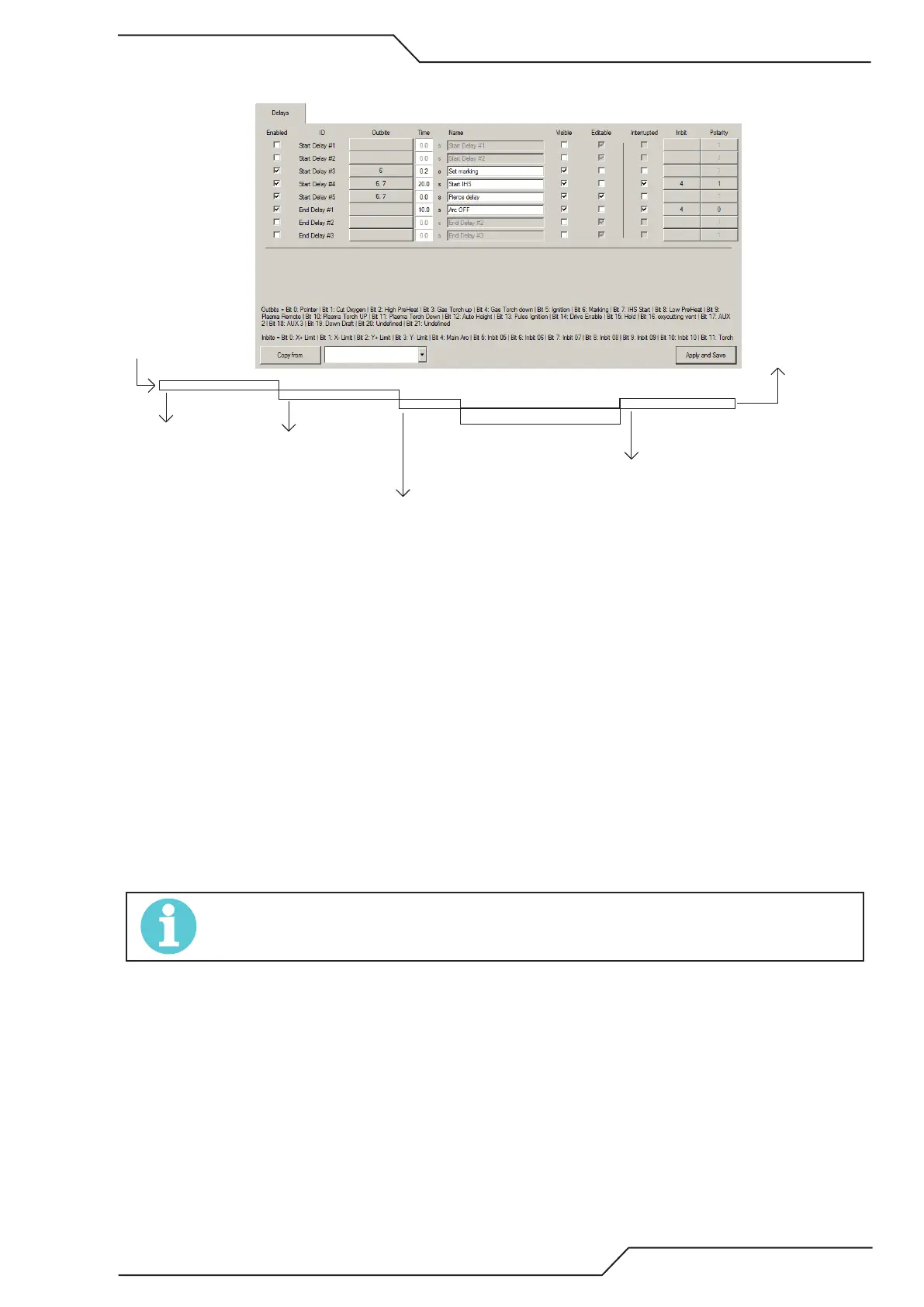
Start Delay is referenced as SD and End delay is referenced as ED.
• Enabled You can Enable/Disable the Delay. In the example picture above SD1-2 are disabled as they are not used.
• ID Delay ID name.
• Outbits Set outbits that are active (ON) during the delay.
• Time Set the default delay time.
• Name Write a delay description.
• Visible Sets if the if the delay visible in the process selection window.
• Editable Sets if the delay can be edited in the process selection window.
* Select if the delay is shown in readjust cutting parameters.
• Interrupted Sets if the delay can be interrupted or just a time based delay.
• Inbit Select the inbit that will be used for delay interruption. In the example picture Inbit4 will interrupt SD4 delay when
it turns 1. Also ED1 will be interrupted when Inbit4 turns back to 0.
• Polarity Set the inbit interrupt polarity.
• Start Not used with plasma cutting. See explanation from gas cutting example.
The example above is a typical I/O map when plasma is used as the marking device.
NOTE!
Only hardwire marking supported.