iCNC Perfromance
Manual 0-5401 I/O 3-1
SECTION 3: I/O DESCRIPTIONS
3.1 General
iCNC Performance provides input and output connectors for external devices. This sections covers the back wall connectors.
You can change the input or output description name in iCNC Settings, instructions how to change setting are later described
in this section.
WARNING
All external relays needs to be powered from the I/O connectors. DO NOT use external power supply to drive external relays!
3.2 J45 Inputs
All inputs are active low, so the input will activate when the input is grounded to the input GND.
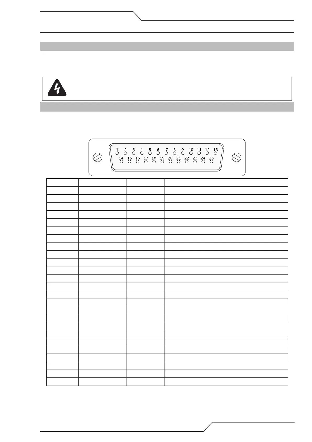
3.2.1 Input Pin Arrangement
Pin number Input number Default name Description
1 Inbit 0 X+ Limit Grounding the input to pin #13/#25 will activate the input
2 Inbit 2 Y+ Limit Grounding the input to pin #13/#25 will activate the input
3 Inbit 4 Ok to Move Grounding the input to pin #13/#25 will activate the input
4 Inbit 6 Servo error Y Grounding the input to pin #13/#25 will activate the input
5 Inbit 8 Inbit 8 Grounding the input to pin #13/#25 will activate the input
6 Inbit 10 Inbit 10 Grounding the input to pin #13/#25 will activate the input
7 Inbit 12 Inbit 12 Grounding the input to pin #13/#25 will activate the input
8 Inbit 13 Inbit 13 Grounding the input to pin #13/#25 will activate the input
9 Inbit 14 Inbit 14 Grounding the input to pin #13/#25 will activate the input
10 Inbit 15 Servo Error Grounding the input to pin #13/#25 will activate the input
11 N/A N/A Not used
12 24VDC Output 24VDC Output max combined current with pin #24 1A
13 GND Signal GND
14 Inbit 1 X- Limit Grounding the input to pin #13/#25 will activate the input
15 Inbit 3 Y- Limit Grounding the input to pin #13/#25 will activate the input
16 Inbit 5 Servo error X Grounding the input to pin #13/#25 will activate the input
17 Inbit 7 Servo error Y2 Grounding the input to pin #13/#25 will activate the input
18 Inbit 9 Inbit 9 Grounding the input to pin #13/#25 will activate the input
19 Inbit 11 Inbit 11 Grounding the input to pin #13/#25 will activate the input
20 N/A N/A Not used
21 N/A N/A Not used
22 N/A N/A Not used
23 N/A N/A Not used
24 24VDC Output 24VDC Output max combined current with pin #12 1A
25 GND Signal GND