iCNC Perfromance
Manual 0-5401 APPENDIX B B-15
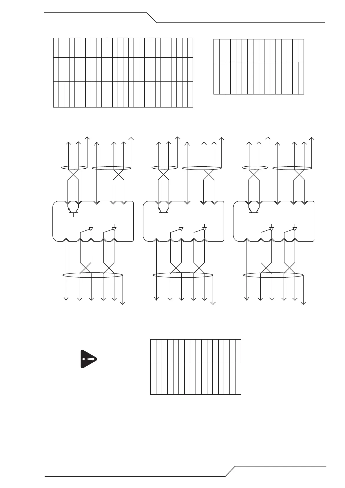
B.4.2 Panasonic A5 Speed Loop Example
Panasonic A5
X4
Y2-axis
SPR
#14
Signal GND
#15
#29
/SRV-ON
+24 VIN
#7
OA+
OA-
OB+
OB-
#21
#22
#48
#49
J47 X- Speed #6
J47 GND #15
Cable shield to J47 connector casing or GND
Cable shield to J48 connector casing or GND
J48 A+ #5
J48 A- #13
J48 B- #14
J48 B+ #6
J47 Enable #14
J48 24VDC #15
#36
#37
Cable shield to J45 connector casing or GND
J45 Inbit 7 #17
J45 GND #25
Pin number Input number Default name
1 Inbit 0 X+ Limit
2 Inbit 2 Y+ Limit
3 Inbit 4 Ok to Move
4 Inbit 6 Inbit 6
5 Inbit 8 Inbit 8
6 Inbit 10 Inbit 10
7 Inbit 12 Inbit 12
8 Inbit 13 Inbit 13
9 Inbit 14 Inbit 14
10 Inbit 15 Servo Error
11 N/A N/A
12 24VDC Output
13 GND
14 Inbit 1 X- Limit
15 Inbit 3 Y- Limit
16 Inbit 5 Inbit 5
17 Inbit 7 Inbit 7
18 Inbit 9 Inbit 9
19 Inbit 11 Inbit 11
20 N/A N/A
21 N/A N/A
22 N/A N/A
23 N/A N/A
24 24VDC Output
25 GND
J45 Inputs
Pin number Name
1 X-Axis Direction +
2 X-Axis Step +
3 Y-Axis Direction +
4 Y-Axis Step +
5 X-Axis Speed
6 Y2-Axis Speed
7 5VDC
8 GND
9 X-Axis Direction -
10 X-Axis Step -
11 Y-Axis Direction -
12 Y-Axis Step -
13 Y-Axis Speed
14 Servo Enable
15 GND
J47 Servo
Pin number Name
1 X-Axis A+
2 X-Axis B+
3 Y-Axis A+
4 Y-Axis B+
5 Y2-Axis A+
6 Y2-Axis B+
7 5VDC
8 GND
9 X-Axis A-
10 X-Axis B-
11 Y-Axis A-
12 Y-Axis B-
13 Y2-Axis A-
14 Y2-Axis B-
15 24VDC
Panasonic A5
X4
Y-axis
SPR
#14
Signal GND
#15
#29
/SRV-ON
+24 VIN
#7
OA+
OA-
OB+
OB-
#21
#22
#48
#49
J47 X- Speed #13
J47 GND #15
Cable shield to J47 connector casing or GND
Cable shield to J48 connector casing or GND
J48 A+ #3
J48 A- #11
J48 B- #12
J48 B+ #4
J47 Enable #14
J48 24VDC #15
Cable shield to J45 connector casing or GND
Panasonic A5
X4
X-axis
SPR
#14
Signal GND
#15
#29
/SRV-ON
+24 VIN
#7
OA+
OA-
OB+
OB-
#21
#22
#48
#49
J47 X- Speed #5
J47 GND #8
Cable shield to J47 connector casing or GND
Cable shield to J48 connector casing or GND
J48 A+ #1
J48 A- #9
J48 B- #10
J48 B+ #2
J47 Enable #14
J48 24VDC #15
Cable shield to J45 connector casing or GND
J48 Encoder
Servo error signals are optional and need to be set in
iCNC setup I/O General
ALM+
ALM-
#36
#37
J45 Inbit 7 #17
J45 GND #25
ALM+
ALM-
#36
#37
J45 Inbit 7 #17
J45 GND #25
ALM+
ALM-