iCNC Perfromance
Manual 0-5401 APPENDIX B B-23
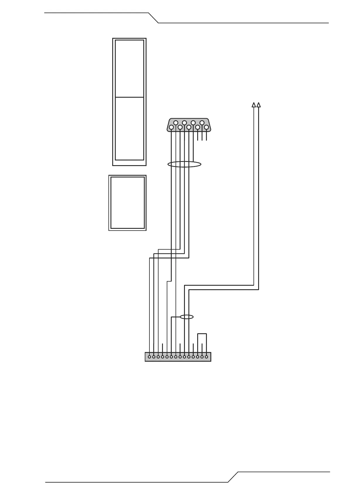
B.4.10 Ultra-Cut XT Communication Cable
3x2x0.25mm²
Label: J54 - TSC/COMM
1
6
2
7
3
8
4
9
5
RS-485
D9 Male (solder)
Wurth 61800924823
Back shell: Wurth 61800925322
3 = TX-
8 = TX+
9 = RX+
4 = RX-
5 = GND
7 = GND
1
2
3
4
5
6
7
8
9
10
11
12
13
14
J54 - TSC/COMM
Connector: AMP 182649-1 (14pin Male Plug)
Pins: AMP 1-66103-8 (pin tin)
Cable Clamp: AMP 1-206070-0 (size 17)
TX+
TX-
RX+
RX-
GND
GND
HMI Plasma Enable SW (white)
HMI Plasma Enable SW (brown)
Shield
Description Cat Part#
Table1
iCNC Perf RS-485 - 25ft 15-6016
15-6017
15-6023
15-6024
iCNC Perf RS-485 - 50ft
iCNC Perf RS-485 - 75ft
iCNC Perf RS-485 - 100ft
Plasma Enable SW1
Plasma Enable SW2
2x1x0.25mm²Label: Plasma Enable
Colors used on RS-485:
Pin9, RX+, white
Pin4, RX-, brown
Pin8, TX+, green
Pin3, TX-, yellow
Pin5, GND, grey
Shield
Wire to a relay controlled by outbit number #5 on J46
On servo adapter card wire to connector Outputs2 terminals 5-NO and 5-COM