iCNC Performance
B-16 APPENDIX B Manual 0-5401
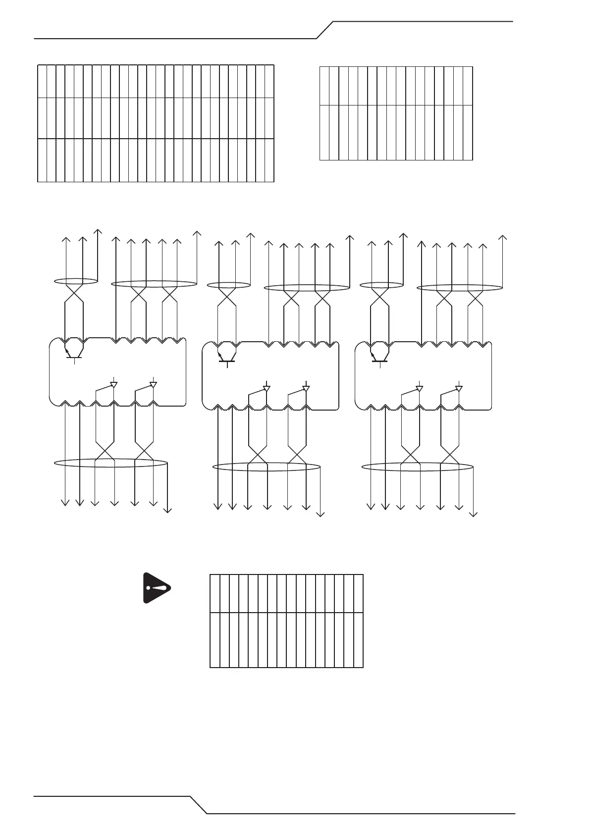
B.4.3 Panasonic A5 STEP/DIR Example
#25
GND
J48 GND #8
#7
COM+
J48 24VDC #15
#25
GND
J48 GND #8
#7
COM+
J48 24VDC #15
#25
GND
J48 GND #8
#36
#37
#21
#22
#48
#49
#7
#21
#22
#48
#49
#36
#37
#6
#5
Panasonic
Minas A5
X4
Y2-axis
PULS 1
#3
PULS 2
#4
#29
SRV-ON
PAO
/PAO
PBO
/PBO
J47 Y STEP- #12
J47 Y STEP+ #4
Cable shield to J47 connector casing or GND
Cable shield to J48 connector casing or GND
J48 A+ #5
J48 A- #13
J48 B- #14
J48 B+ #6
J47 Enable #14
ALM+
ALM-
Cable shield to J45 connector casing or GND
J45 Inbit 7 #17
J45 GND #13
SIGN 1
SIGN 2
J47 Y DIR- #11
J47 Y DIR+ #3
#6
#5
Panasonic
Minas A5
X4
Y-axis
PULS 1
#3
PULS 2
#4
SRV-ON
COM+
OA+
OA-
OB+
OB-
J47 Y STEP- #12
J47 Y STEP+ #4
Cable shield to J47 connector casing or GND
Cable shield to J48 connector casing or GND
J48 A+ #3
J48 A- #11
J48 B- #12
J48 B+ #4
J47 Enable #14
J48 24VDC #15
ALM+
ALM-
Cable shield to J45 connector casing or GND
J45 Inbit 6 #4
J45 GND #13
SIGN 1
SIGN 2
J47 Y DIR- #11
J47 Y DIR+ #3
Pin number Input number Default name
1 Inbit 0 X+ Limit
2 Inbit 2 Y+ Limit
3 Inbit 4 Ok to Move
4 Inbit 6 Inbit 6
5 Inbit 8 Inbit 8
6 Inbit 10 Inbit 10
7 Inbit 12 Inbit 12
8 Inbit 13 Inbit 13
9 Inbit 14 Inbit 14
10 Inbit 15 Servo Error
11 N/A N/A
12 24VDC Output
13 GND
14 Inbit 1 X- Limit
15 Inbit 3 Y- Limit
16 Inbit 5 Inbit 5
17 Inbit 7 Inbit 7
18 Inbit 9 Inbit 9
19 Inbit 11 Inbit 11
20 N/A N/A
21 N/A N/A
22 N/A N/A
23 N/A N/A
24 24VDC Output
25 GND
J45 Inputs, mating connector
25pin D-Sub female
Pin number Name
1 X-Axis Direction +
2 X-Axis Step +
3 Y-Axis Direction +
4 Y-Axis Step +
5 X-Axis Speed
6 Y2-Axis Speed
7 5VDC
8 GND
9 X-Axis Direction -
10 X-Axis Step -
11 Y-Axis Direction -
12 Y-Axis Step -
13 Y-Axis Speed
14 Servo Enable
15 GND
J47 Servo, mating connector
25pin D-Sub female
Pin number Name
1 X-Axis A+
2 X-Axis B+
3 Y-Axis A+
4 Y-Axis B+
5 Y2-Axis A+
6 Y2-Axis B+
7 5VDC
8 GND
9 X-Axis A-
10 X-Axis B-
11 Y-Axis A-
12 Y-Axis B-
13 Y2-Axis A-
14 Y2-Axis B-
15 24VDC
J48 Encoder, mating connector
25pin D-Sub male
- Servo error signals need to be set in iCNC setup I/O General.
- If encoders are not used disregard drawing encoder connections.
- Verify your speed/step/encoder settings
from icncSetup Drive configuration.
- Y2 motor polarity needs to be changed from the servo amplifier.
#6
#5
Panasonic
Minas A5
X4
X-axis
PULS 1
#3
PULS 2
#4
#29
SRV-ON
OA+
OA-
OB+
OB-
#21
#22
#48
#49
J47 X STEP- #10
J47 X STEP+ #2
Cable shield to J47 connector casing or GND
Cable shield to J48 connector casing or GND
J48 A+ #1
J48 A- #9
J48 B- #10
J48 B+ #2
J47 Enable #14
ALM+
ALM-
#36
#37
Cable shield to J45 connector casing or GND
J45 Inbit 5 #16
J45 GND #13
SIGN 1
SIGN 2
J47 X DIR- #9
J47 X DIR+ #1
#29