iCNC Performance
7-16 iCNC SETUP Manual 0-5401
• External stop inbits Enable, select external stop trigger inbits and their polarities. Activating an external stop will prompt
inbit name, stop motion and cutting.
• Servo error Enable, select servo error trigger inbits and their polarities. Activating a servo error inbit will prompt inbit
name, turns enable outbit off and stops cutting process. If the Teknic check box is checked inbit has to turn on after
enable output has been turned on.
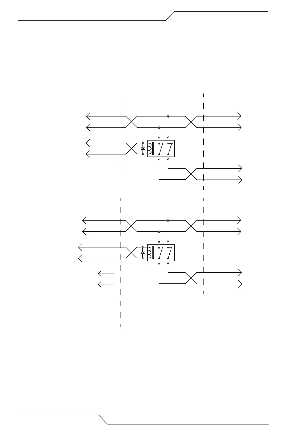
NC
24VDC Double Pole Relay
With Back EMF diode
J46 Outbit X
J46 24VDC #24
J47 #4 STEP Y+
J47 # 10 STEP Y-
Y2 Servo STEP+ Y2
Y2 Servo STEP- Y2
Y Servo STEP Y+
Y Servo STEP Y-
iCNC PERFORMANCE SERVO DRIVES
Wiring from iCNC Performance
NC
24VDC Double Pole Relay
With Back EMF diode
OUTPUTS X #XX-NO (2)
CTRL Y #2 STEP +
CTRL Y #6 STEP Y-
Y2 Servo STEP+ Y2
Y2 Servo STEP- Y2
Y Servo STEP Y+
Y Servo STEP Y-
Servo adapater PCB SERVO DRIVES
SPEED Y #5 24VDC
INPUTS X #GND
(3)
OUTPUTS X #XX-COM (3)
1) See cable axample for wiring to
servo adapter pcb in appendix B
2) Select a spare output from the
servo adapter PCB (available outbits 9, 16, 19).
Output needs to be set in iCNCsetup -->
IO General
3) Select a spare GND from the input
connector and wire to output COM
that is used in 2)
See appendix B for details about
the servo adapater card.
Wiring from servo adapter card
Y2 alignment with STEP/DIR signals