FM-750 Display User Guide 99
Mapping and Guidance 6
When you define the first guidance line, the display copies it to create additional
guidance lines.
Distance between guidance lines
When you define the AB line, you specify the width of the implement that is attached
to the vehicle. The display uses this measurement to calculate the distance between
the guidance lines. If you do not want the guidance lines to be exactly one implement
width apart, you can set an overlap or skip.
Headlands
You can record a headland boundary, or you can work without a headland.
On screen appearance
When the guidance screen shows the trailing view, it tags the guidance lines with the
following icons:
Guidance Patterns
Select a guidance pattern that enables you to create a guidance line to suit your field:
1. From the guidance screen, tap and then tap
Create New Field.
2. In the Create New Field screen, tap
Pattern Type:
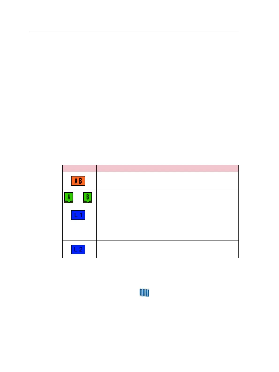
These icon/s Are tagged to ...
The master line that you created. The swaths are based on this line.
The A (start) and B (end) point on the master line.
The first swath to the left of the master line, where ‘left’ is relative to the
direction the master line was drawn, not the vehicle's current position.
Note the following:
• The current swath and tag are orange.
• On a Pivot pattern, the swaths are numbered out from the center, not
from the initial swath.
The second line to the left of the master line.