Motion Coordinator Technical Reference Manual
Daughter Boards 4-21
Stepper Encoder Daughter
Reference Encoder Input
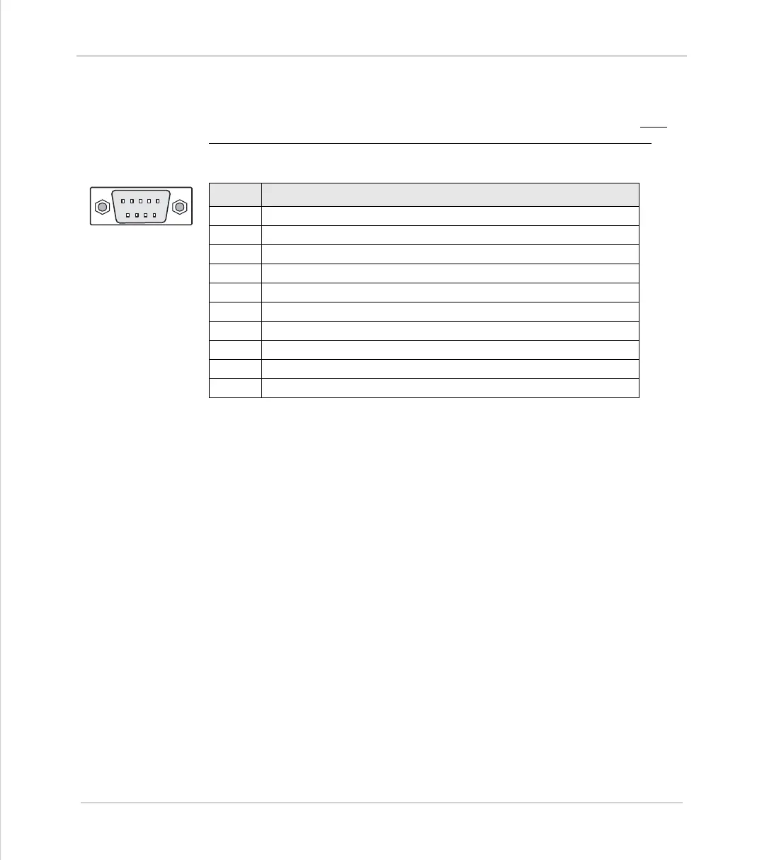
The encoder is connected via a 9 pin 'D' type socket mounted on the front panel.
The plug supplied should be cable mounted and wired as shown below. The
encoder port is designed for use with differential output 5 volt encoders.
The encoder may be powered from the +5V supply output on the daughter board,
provided it requires less than 150mA supply current. If the encoder is situated so
far from the module that the supply is inadequate an external supply should be
used and regulated locally to the encoder. In this case the +5V connection from
pin 8 should not be used and the external supply 0v should be connected to pin 5
(0V).
If the encoder does not have complementary outputs, pins 2, 4 and 7 should be
connected to a +2.5V bias voltage. This may be simply derived from a pair of 220
Ohm resistors in series with one end of the pair connected to 0v and the other
end to +5v. The centre point of the pair will form approximately 2.5v.
If the encoder does not have a marker pulse, pins 6 and 7 may be left uncon-
nected.
Pin. function
1
channel A true
2
channel A complement
3
channel B true
4
channel B complement
5
0V
6
marker (Z) true
7
marker (Z) complement
8
+5V (150 mA max) - This output is short circuit protected
9
Registration Input 5v Input pin
shell
protective ground
5 4 3 2 1
9 8 7 6