TITANUS MICRO·SENS
®
Installation
MS_A_05-en-e Data: 01/09 5 – 17
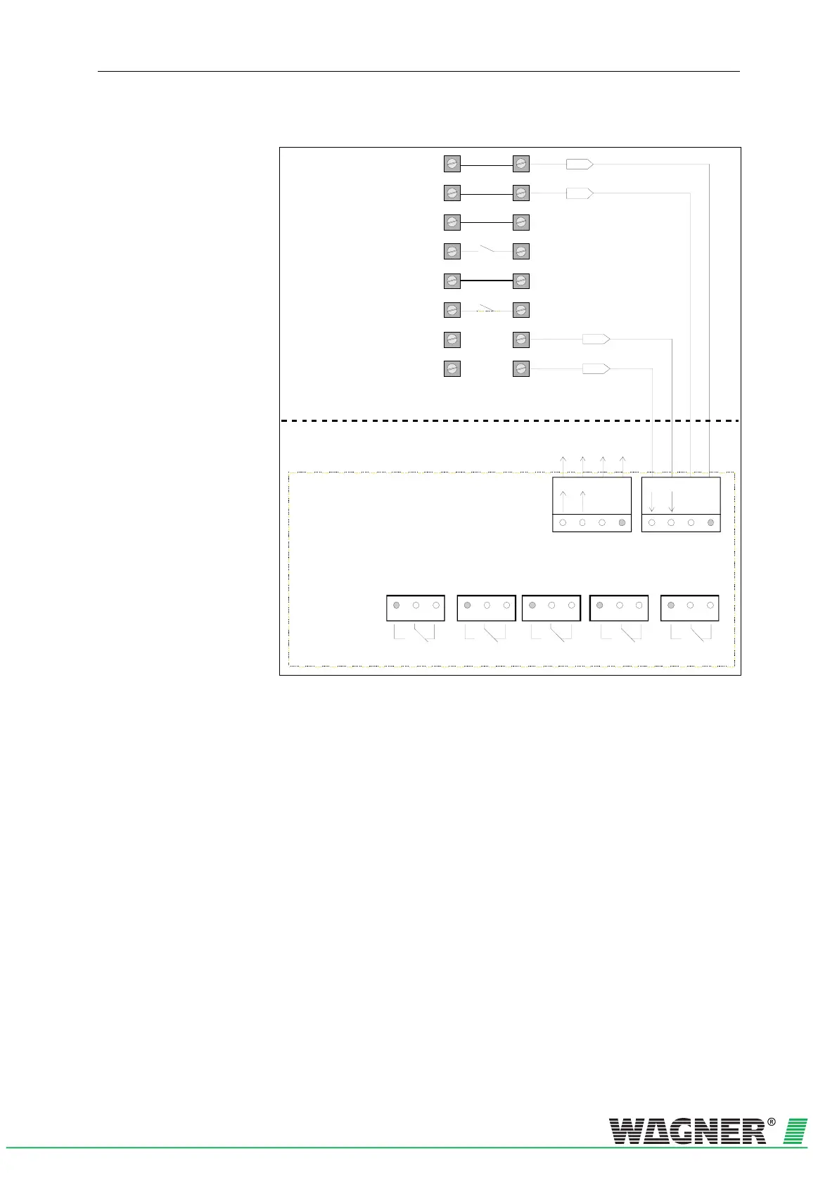
5.7.2 Function switching plan, relay board RU-2
0V
1a
2a
3a
4a
5a
6a
7a
8a
1b
2b
3b
4b
5b
6b
7b
8b
+24V
Indikatorbus
X5X4X3X2
X1
NC
COM
NO
X9X8
+24V
GND
Data
A
B
+24V
GND
A
B
Relay board RU-2
NC
COM
NO
NC
COM
NO
NC
COM
NO
NC
COM
NO
action alarm Fire alarm fault
Data
to the next
board or
parallel display
Additi onal housing
Device Base detection unit
action alarm Fire alarm
Fig. 5.16: Example of TITANUS MICRO·SENS
®
connections with relay board RU-2

 Loading...

