TITANUS MICRO·SENS
®
Installation
MS_A_05-en-e Data: 01/09 5 – 7
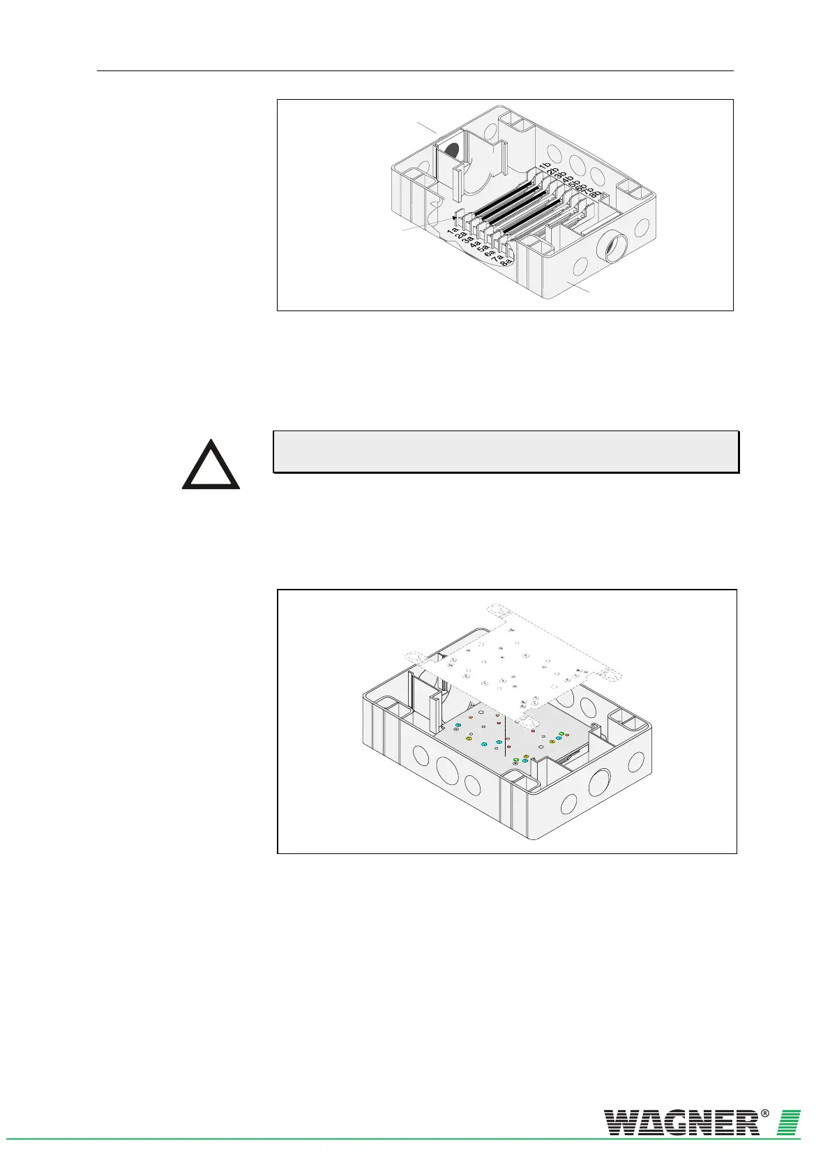
Device base unit
Te r m i n a l b l o c k
Aspiration pipe
connection
Fig. 5.6: Arrangement of screw terminals in the device base unit
Alarm and fault contact can be used, for example, to connect to a CFDU
or to control signals, guidance systems etc. There is also the option of
connecting a parallel display or reaction indicators to the device indicator
bus.
Permanent wiring in the reset input leads to all messages being auto-
matically reset when the cause of the message has been removed.
Additional housing If additional modules or a parallel display are used, then an installation
plate is screwed into the base unit of the additional housing.
Fig. 5.7: Positioning of the installation plate in the additional housing base unit
INSTRUCTION
 Loading...


