Installation TITANUS MICRO·SENS
®
5 – 6 Data: 01/09 MS_A_05-en-e
5.3 Incorporation and electrical connection
of additional modules
To prepare the electrical connections, the following steps must first be
taken:
1. Make the number of cable entries required on the device base unit,
e.g. with a screwdriver.
2. Put the cable entries M20 and/or M25 into the corresponding cable
holes.
3. Feed the cable through the corresponding cable holes.
2x M20 and 1x M25 cable entries are supplied with the device.
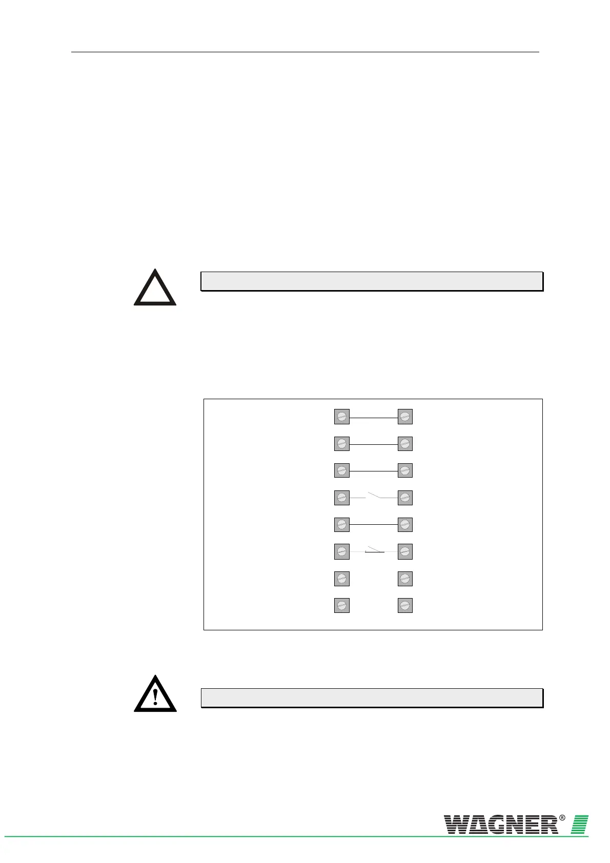
The electrical connection is made via screw terminals 1a to 8a and 1b to
8b on the TITANUS MICRO·SENS
®
base unit. In so doing, note the per-
mitted cable cross-sections on the threaded joints and the permitted wire
cross-sections on the terminals for a max. 0.5 mm²-2.5 mm² wires.
Reset +
Reset -
0V
1a
2a
3a
4a
5a
6a
7a
8a
1b
2b
3b
4b
5b
6b
7b
8b
+24V
Indicator bus
Alarm relay
Fault relay
Fig. 5.5 : Layout of screw terminals in the device base unit
Carry out all connection work to the device with the power off!
INSTRUCTION
ATTENTION
 Loading...


