430 Ink Jet Printer Service and Maintenance Manual
68
Issue 2
Part No. 306-0430-102
PIGS (
9
) - Will be used in future models for an ink heater/cooler system.
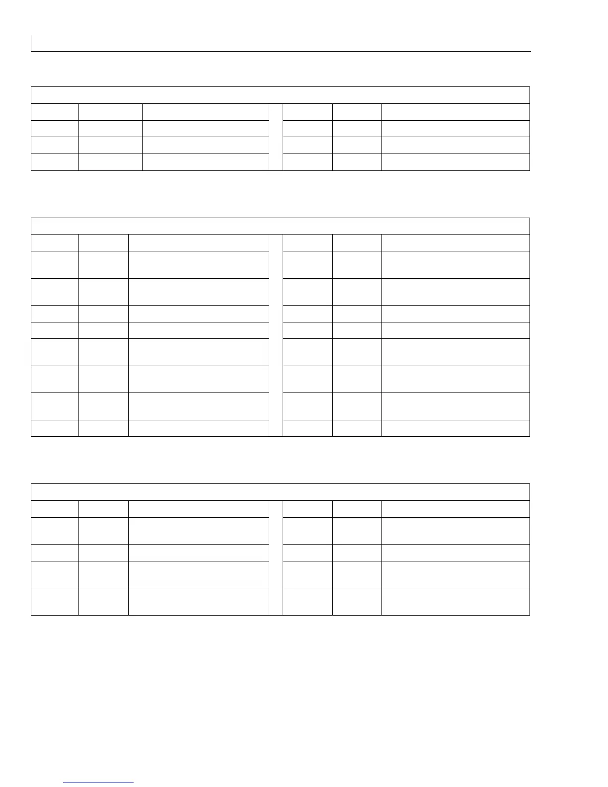
Pin No. Signal Function Pin No. Signal Function
1 +24 V 4 0 V
2 BULK HEAT 5 HEATER Heater/cooler on/off
3 +24 V 6 0 V
Table 19 I/O Connector PIGS
VALVES (
10
) - Ink system solenoid valves.
Pin No. Signal Function Pin No. Signal Function
1 +24 V +24 V DC to solvent top up
valve V1
9 +24 V +24 V DC to feed valve V6
2 - ve Solvent top up valve control
signal
10 - ve Ink feed valve control signal
3 +24 V +24 V DC to Ink top up valve V2 11 +24 V +24 V DC to gutter valve V8
4 - ve Ink top up valve control signal 12 - ve Gutter valve control signal
5 +24 V +24 V DC to VMS diverter valve
V3
13 +24 V +24 V DC auto power off
6 - ve VMS diverter valve control
signal
14 - ve Auto power off control signal
7 +24 V +24 V DC to solvent flush valve
V4
15 +24 V +24 V DC to purge valve V10
8 - ve Solvent flush valve control signal 16 - ve Purge valve control signal
Table 20 I/O Connector VALVES
CON_BM2 (
11
) - Ink pump motor driver board.
Pin No. Signal Function Pin No. Signal Function
1 B OUT Stator drive B (green) 5 HC Position signal from Hall effect
sensor C (green)
2 A OUT Stator drive A (black) 6 0 V Hall effect sensor -ve supply
3 C OUT Stator drive C (white) 7 HB Position signal from Hall effect
sensor B (white)
4 +6 V Hall effect sensor +ve supply 8 HA Position signal from Hall effect
sensor A (blue)
Table 21 I/O Connector CON_BM2