Technical Description: Control Electronics
Issue 2
69
Part No. 306-0430-102
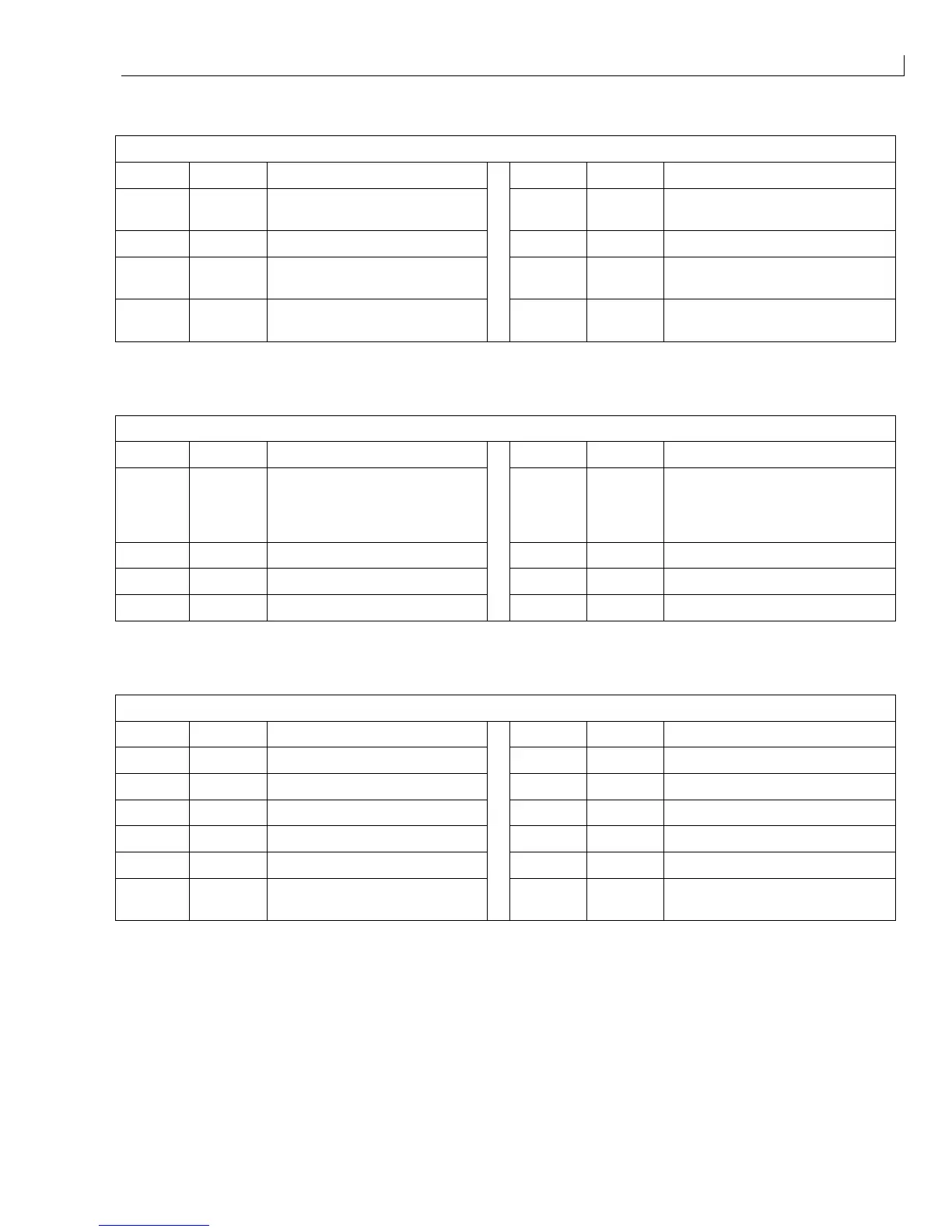
PUMP (
12
) - Ink system pump.
Pin No. Signal Function Pin No. Signal Function
1 B OUT Stator drive B 5 HC Position signal from Hall effect
sensor C
2 A OUT Stator drive A 6 0 V Hall effect sensor -ve supply
3 C OUT Stator drive C 7 HB Position signal from Hall effect
sensor B
4 +6 V Hall effect sensor +ve supply 8 HA Position signal from Hall effect
sensor A
Table 22 I/O Connector CON_BM2
P/TRANS (
13
) - Ink system temperature sensor and the pressure transducer.
Pin No. Signal Function Pin No. Signal Function
1 +10 V +10 V DC supply voltage to
transducer
5BULK
INK
TEMPER
ATURE
Output from mixer tank
temperature sensor
2 +ve +ve output from transducer 6 0 V 0 V to temperature sensor
3 - ve - ve output from transducer 7 +5 V +5 V DC to temperature sensor
4 0 V 0 V to transducer 8 GND
Table 23 I/O Connector P/TRANS
HEAD_2 (
14
) - Printhead connector 2 via the umbilical.
Pin No. Signal Function Pin No. Signal Function
1 VCC +5 V DC 7 0 V
2 Not used 8 +5 V +5 V DC to temp sensor
3 Not used 9 HE temp Head temp sensor output
4 0 V 10 0 V 0 V to temp sensor
5 VCC +5 V DC 11 Head heater return
6Fire
sensor
Fire sensor (not used at present) 12 +24 V +24 V to head heater
Table 24 I/O Connector HEAD_2