430 Ink Jet Printer Service and Maintenance Manual
70
Issue 2
Part No. 306-0430-102
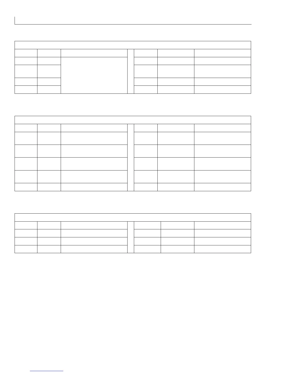
CON_BM1 (
15
) - Ink pump motor driver board.
Pin No. Signal Function Pin No. Signal Function
1 +24 V 5 ENABLE Enable ink pump motor
2 0 V 6 PRESS TRANS
I/P
Pressure transducer input
3 +15 V 7 REQ PRESS I/P Requested pressure input
4 - 15 V
Supplies to motor control board
8GND
Table 25 I/O Connector CON_BM1
HEAD_1 (
16
) - Printhead connector 1 via the umbilical.
Pin No. Signal Function Pin No. Signal Function
1 +12 V +12 V DC to phase detector
amplifier
6 0 V 0 V connection to LED
cathodes
2 - 12 V - 12 V DC to phase detector
amplifier
7 STROBE LED Strobe signal to LED
anode
3 0 V 0 V connection to phase
detector amplifier
8 Signal from phase detector
amp
4 GUTTER
DETECT
Oscillator signal to gutter detect 9 LID SWITCH +ve to lid switch
5 0 V 0 V connection to gutter detect 10 0 V 0 V connection to lid switch
Table 26 I/O Connector HEAD_1
CON_P0 (
17
) - Interboard connector from I/O board to CPU board. It carries the DC voltages from the PSU
Pin No. Signal Function Pin No. Signal Function
1 to 4 0 V 0 V 11 and 12 - 15 V - 15 V DC to CPU
5 to 8 +5 V +5 V DC to CPU 13 and 14 GND
9 and 10 +15 V +15 V DC to CPU
Table 27 I/O Connector CON_P0