Technical Description: Control Electronics
Issue 2
71
Part No. 306-0430-102
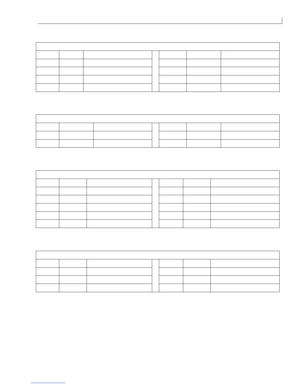
POWER (
18
) - PSU.
Pin No. Signal Function Pin No. Signal Function
1 15 V 15 V DC from PSU 5 +5 V +5 V DC from PSU
2 0 V 0 V from PSU 6 +24 V +24 V DC from PSU
3 +5 V +5 V DC from PSU 7 0 V 0 V from PSU
4 - 15 V - 15 V DC from PSU 8 - 24 V - 24 V DC from I/O board
Table 28 I/O Connector POWER
CH/MOD (
19
) - Printhead via the umbilical.
Pin No. Signal Function Pin No. Signal Function
1 CHARGE Charge amplifier output 3 mod 1a Modulation 0 V
2 0 V CHARGE Charge amplifier 0 V 4 mod 1b Modulation signal output
Table 29 I/O Connector CH/MOD
EHT/FAN (
20
) - Cooling fan and EHT module.
Pin No. Signal Function Pin No. Signal Function
1 0 V 0 V 6 EHT + +ve supply to EHT module
2 +24 V SW +24 V DC (switched) 7 EHT - - ve supply to EHT module
3 PUMP +24 V DC 8 VCC +5 V DC
4 +24 V SW + 24 V DC (switched) fan 9 Lev 8 Spare digital input
5 FAN - ve fan supply 10 0 V 0 V
Table 30 I/O Connector EHT/FAN
FAN_FAIL (
21
) - Fan failure sensor PCB.
Pin No. Signal Function Pin No. Signal Function
1 +ve in Fan fail +ve input 4
2 +5 V +5 V DC supply to fan fail PCB 5 0 V 0 V supply to fan fail PCB
3 6 - ve in Fan fail -ve input
Table 31 I/O Connector FAN_FAIL