430 Ink Jet Printer Service and Maintenance Manual
72
Issue 2
Part No. 306-0430-102
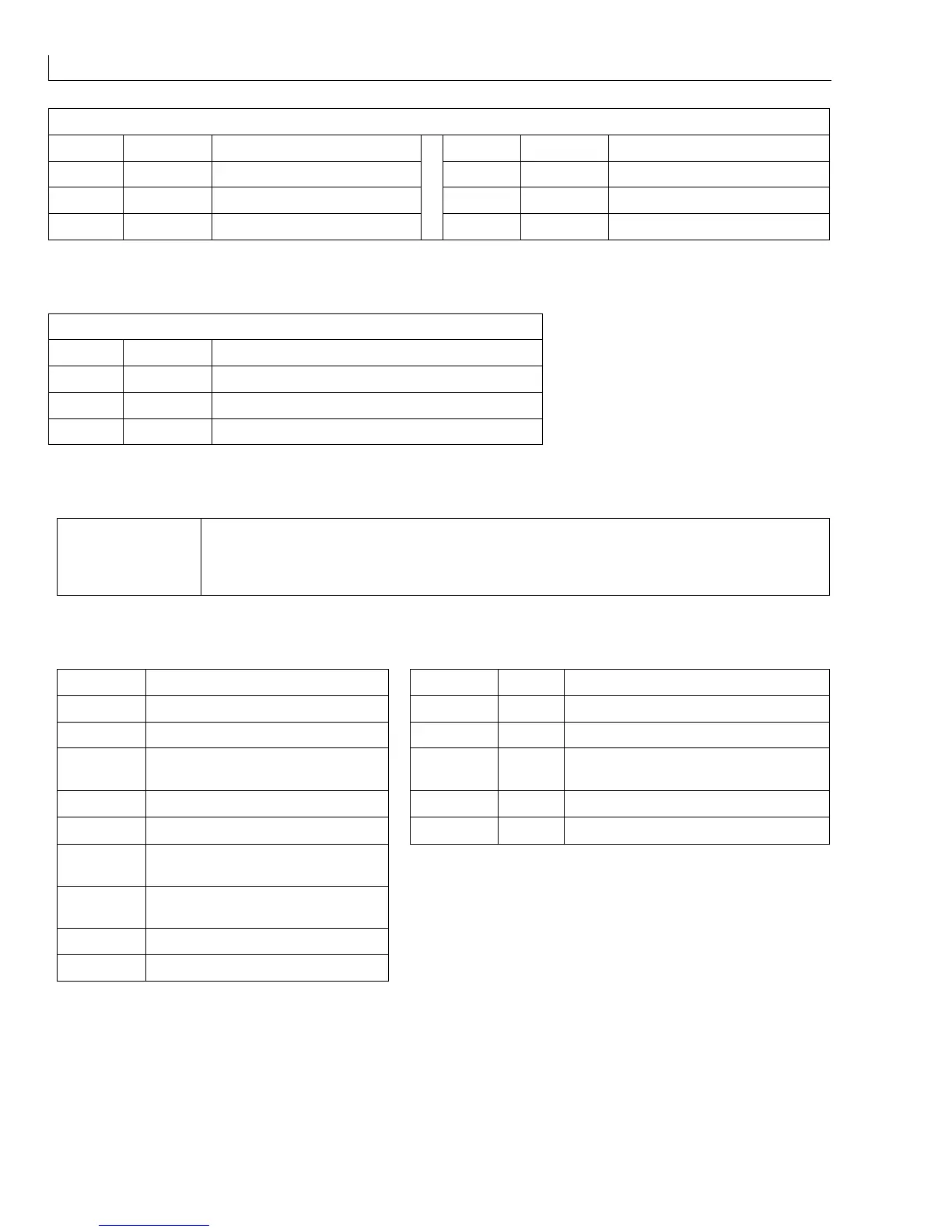
CON_D (
22
) - Interboard connector from I/O board to CPU board.
Pin No. Signal Function Pin No. Signal Function
1 to 8 dd0 to dd7 Droplet charge data 10 0 V Common
9 - Not used 11-20 - Not used
Table 32 I/O Connector CON_D
B/LIGHT (
23
) -
Backlight of the Liquid Crystal Display (LCD).
Pin No. Signal Function
1 +24 V +24 V DC to backlight inverter
2 - ve BKLT Backlight -ve supply
3GND
Table 33 I/O Connector B/LIGHT
JB1 Used to configure the photocell inputs PEC1 and PEC2.
PEC1 is connected to product error 1 via the connector panel.
PEC2 is connected to product error 2 via the connector panel.
Table 34 I/O Board Jumper
Test point Signal LED Colour Function
TP1 (
14
)
0 V.
LED1 (
11
)
green Customer 10 V isolated supply present.
TP2 (
8
)
+285 V DC charge amplifier supply.
LED2 (
9
)
red Charge amplifier supply.
TP3 (
12
)
Ink temperature at viscometer
delivery line.
LED3 (
6
)
yellow -24 V.
TP4 (
7
)
Charge voltage to printhead.
LED4 (
5
)
red -15 V charge amplifier.
TP5 (
13
)
Ink system pressure (1 V
≈
1 bar).
LED5 (
10
)
green +24 V valve/fan/heater supply.
TP6 (
3
)
Modulation drive voltage to
printhead.
TP7 (
2
)
Phase detector output prior to
hedgehog clipping.
TP8 (
4
)
0 V.
TP9 (
1
)
+5 V (can be used with logic probe).
Table 35 I/O Board Test Points and LEDs