5.3 Sequence I/O Signals
5.3.1 Input Signals
5-11
/JOGP (Forward Jog Input) Signal
This signal functions as the forward jog operation command.
Note: Use PnBA3 = n.X (/JOGP (Forward Jog Input) Signal Allocation) to allocate the /JOGP signal to another
connector pin. Refer to the following section for details.
5.3.3 Allocating Input Signals to Pins and Parameter Settings on page 5-18
/JOGN (Reverse Jog Input) Signal
This signal functions as the reverse jog operation command.
Note: Use PnBA4 = n.X (/JOGN (Reverse Jog Input) Signal Allocation) to allocate the /JOGN signal to another
connector pin. Refer to the following section for details.
5.3.3 Allocating Input Signals to Pins and Parameter Settings on page 5-18
/HOME (Homing Input) Signal
This signal functions as the homing command.
Note: Use PnBA5 = n.X (/HOME (Homing Input) Signal Allocation) to allocate the /HOME signal to another
connector pin. Refer to the following section for details.
5.3.3 Allocating Input Signals to Pins and Parameter Settings on page 5-18
/PGMRES (Program Table Operation Reset Input) Signal
This signal resets program table operation if it turns ON during program table operation. The
motor will decelerate to a stop according to the deceleration rate (DEC) for the current program
step.
Note: Use PnBA6 = n.X (/PGMRES (Program Table Operation Reset Input) Signal Allocation) to allocate the
/PGMRES signal to another connector pin. Refer to the following section for details.
5.3.3 Allocating Input Signals to Pins and Parameter Settings on page 5-18
/SEL0 to /SEL5 (Program Step Selection Input) Signals
These signals specify the program step.
Note: Use PnBA7 = n.X to PnBAC = n.X (/SEL0 to /SEL5 (Program Step Selection Inputs) Signal Allo-
cations) to allocate the /SEL0 to /SEL5 signals to other connector pins. Refer to the following section for
details.
5.3.3 Allocating Input Signals to Pins and Parameter Settings on page 5-18
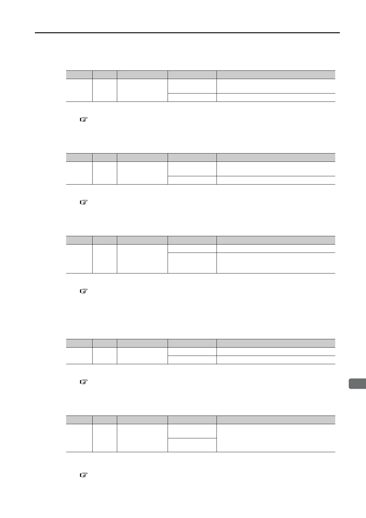
Typ e Signal Pin Signal Status Meaning
Input /JOGP 9 [default setting]
ON (closed)
Forward jog operation is performed. Jog oper-
ation is performed as long as the signal is ON.
OFF (open) Forward jog operation is not performed.
Typ e Signal Pin Signal Status Meaning
Input /JOGN 10 [default setting]
ON (closed)
Reverse jog operation is performed. Jog oper-
ation is performed as long as the signal is ON.
OFF (open) Reverse jog operation is not performed.
Typ e Signal Pin Signal Status Meaning
Input /HOME 6 [default setting]
ON (closed) Homing is started.
OFF (open)
The current status is maintained. Confirm that
the /BUSY signal has turned ON before you
turn OFF this signal.
Typ e Signal Pin Signal Status Meaning
Input
/PGM-
RES
8 [default setting]
ON (closed) Program table operation is reset.
OFF (open) Program table operation is not reset.
Typ e Signal Pin Signal Status Meaning
Input
/SEL0
to
/SEL5
9 to 14
[default settings]
ON (closed)
ON = 1, OFF = 0
The /SEL0 to /SEL5 signals specify a 6-bit
binary number. SEL0 to SEL5 are used to
specify the step number in the program table.
OFF (open)
 Loading...


