5.3 Sequence I/O Signals
5.3.2 Output Signals
5-14
Setting the Output Timing of the /INPOSITION (Positioning Completion
Output) Signal
You can add a reference input condition to the output conditions for the /INPOSITION signal to
change the signal output timing.
/POUT0 to /POUT5 (Program Step Number Output) Signals
These signals indicate the number of the program step that is currently being executed.
Note: Use PnBC1 = n.X to PnBC6 = n.X (/POUT0 to /POUT5 (Program Step Number Outputs) Signal
Allocations) to allocate the /POUT0 to /POUT5 signals to other connector pins. Refer to the following section
for details.
5.3.4 Allocating Output Signals to Pins and Parameter Settings on page 5-20
/WARN (Warning Output) Signal
This signal is for a warning issued before the occurrence of an alarm.
Note: 1. The SERVO OFF state is not entered when a warning occurs.
2. You must allocate the /WARN signal to use it. Use PnBC9 = n.X (/WARN (Warning Output) Signal
Allocation) to allocate the signal to a connector pin. Refer to the following section for details.
5.3.4 Allocating Output Signals to Pins and Parameter Settings on page 5-20
/BK (Brake Output) Signal
This signal functions as the brake operation command. Use it when it is necessary to achieve a
brake system in the equipment driven by the motor.
The Servomotor does not have its own brake. Prepare a brake system in your equipment as
required using this signal.
Note: You must allocate the /BK signal to use it. Use PnBCA = n.X (/BK (Brake Output) Signal Allocation) to
allocate the signal to a connector pin. Refer to the following section for details.
5.3.4 Allocating Output Signals to Pins and Parameter Settings on page 5-20
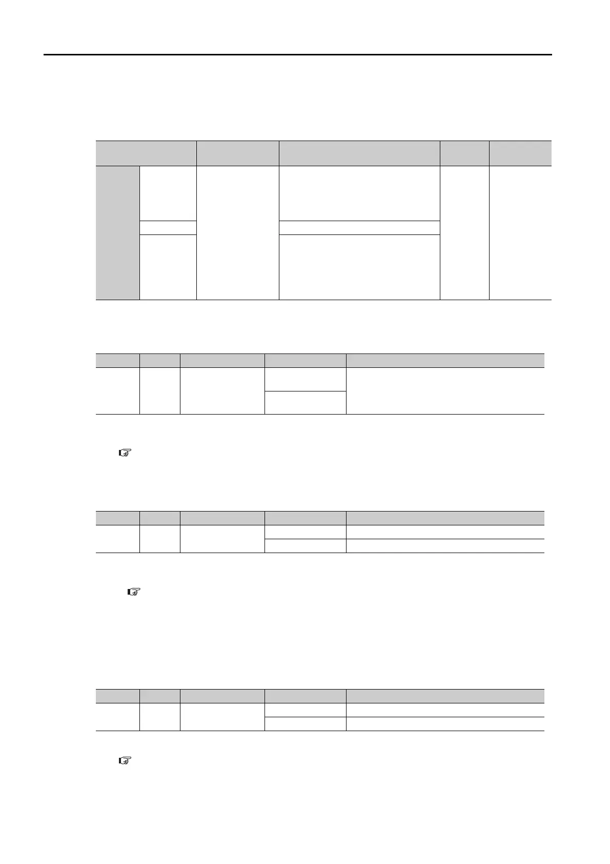
Parameter Name Description
When
Enabled
Classifica-
tion
Pn207
n. 0
[default
setting]
/INPOSITION
(Positioning Com-
pletion Output)
Signal Output
Timing
Output the /INPOSITION signal when
the absolute value of the position
deviation is the same or less than the
setting of PnB2D (Positioning Com-
pleted Width).
After
restart
Setup
n. 1
Reserved setting (Do not use.)
n. 2
Output the /INPOSITION signal when
the absolute value of the position
deviation is the same or less than the
setting of PnB2D (Positioning Com-
pleted Width) and the reference input
is 0.
Type Signal Pin Signal Status Meaning
Output
/POUT0
to
/POUT5
20 to 25
[default settings]
ON (closed)
ON = 1, OFF = 0
The /POUT0 to /POUT5 signals give a 6-bit
binary number. POUT0 to POUT5 specify a
step number in the program table.
OFF (open)
Type Signal Pin Signal Status Meaning
Output /WARN Must be allocated.
ON (closed) Warning
OFF (open) Normal status
Type Signal Pin Signal Status Meaning
Output /BK Must be allocated.
ON (closed) Releases the brake.
OFF (open) Operates the brake.
 Loading...


