4-21
IM 760201-01E
Measurement Conditions
3
2
1
4
5
6
7
8
9
10
11
12
13
14
App
Index
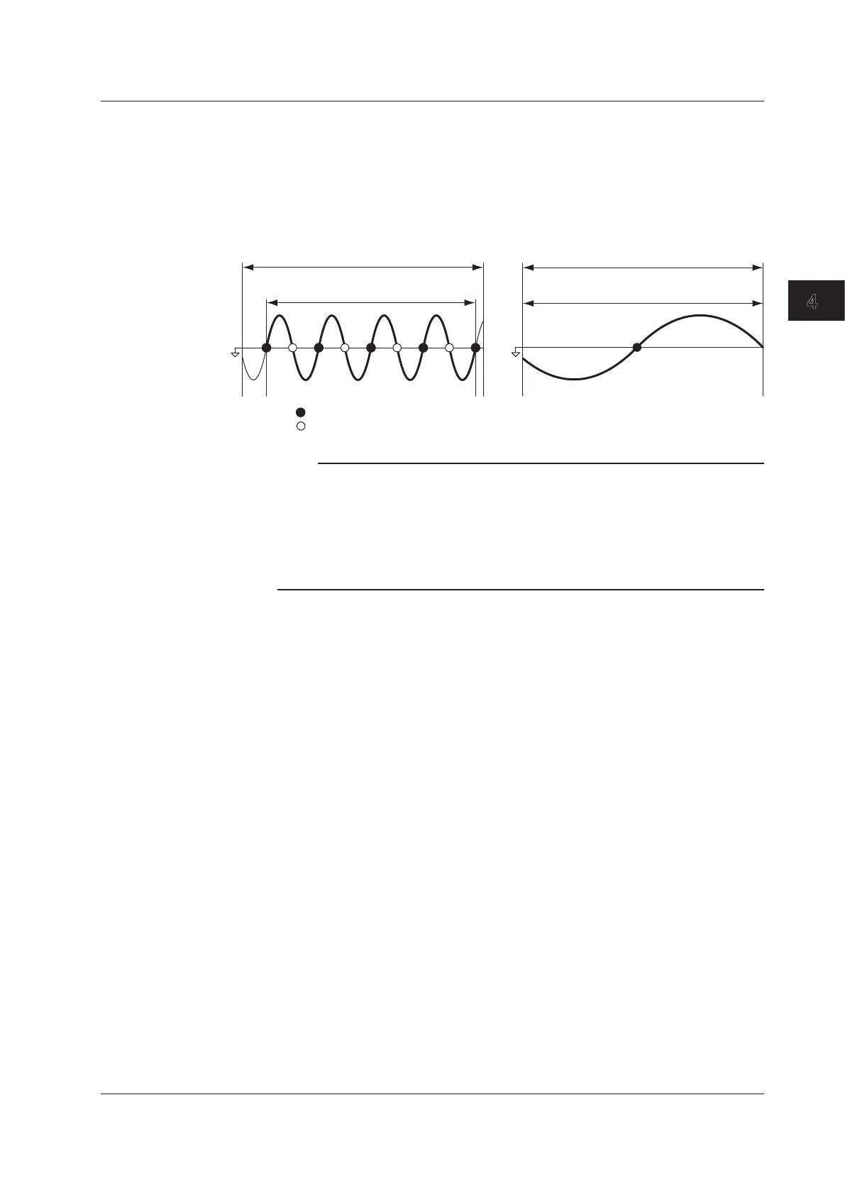
Measurement Period
The measurement period is set within the data update interval between the first point
where the synchronization source crosses the level-zero point (center of the amplitude)
on a rising slope (or falling slope) and the last point where the synchronization source
crosses the level-zero point (center of the amplitude) on a rising slope (or falling slope). If
there is not more than one rising or falling slope within the data update interval, the entire
data update interval is set as the measurement period. For details, see appendix 5.
Data update interval
Measurement period
Sync source
Rising zero crossing
Falling zero crossing
Data update interval
Measurement period
Note
• The measurement period for determining the numeric data of the peak voltage or peak
current is the entire span of the data update interval, regardless of the above settings.
Therefore, the measurement period for the measurement functions that are determined
using the maximum voltage or current value (U+pk, U-pk, I+pk, I-pk, CfU, CfI, FfU, and FfI)
is also the entire span of the data update interval.
• If the synchronization source is not set correctly, the measured value may fluctuate or be
incorrect. Refer to appendix 5 when setting the synchronization source.
4.7 Setting the Measurement Period

 Loading...


