3.9 Wiring the Circuit That You Will Measure for
Direct Input
This section explains how to wire the measurement cable directly from the circuit that
you will measure to the voltage or current input terminal.
To avoid electric shock and damage to the instrument, follow the precautions given in
section 3.5, “Precautions for Wiring the Circuit That You Will Measure.”
Connecting to the Input Terminal
Voltage Input Terminal
The terminal is a
f
4-mm safety banana jack (female).
Insert the safety terminal (whose conductive parts are not exposed) into the voltage input
terminal.
If you are using the 758931 Safety Terminal Adapter that comes with the package, see
section 3.6.
Current Input Terminal
• When the voltage of the circuit under measurement is being applied to the current
input terminals, do not touch the current sensor input terminals. Doing so is dangerous
because the terminals are electrically connected inside the instrument.
•
When connecting measurement cables from external current sensors to current
sensor input connectors, remove the cables connected to the current input terminals.
In addition, when the voltage of the circuit under measurement is being applied to
current sensor input terminals, do not touch the current input terminals. Doing so is
dangerous because the terminals are electrically connected inside the instrument.
•
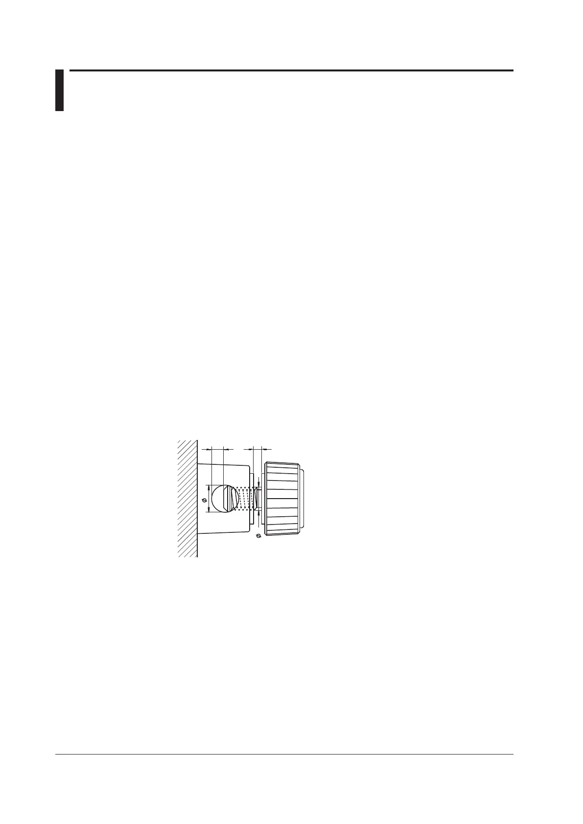
The terminal is a binding post, and the screws are M6. Either wind the wire around the
screw or pass the crimp-on lugs through the screw axis, then tighten firmly with the
terminal knob.
Number of Installed Input Elements and Wiring Systems
The selectable wiring systems vary depending on the number of installed elements. For
example, the three-phase, four-wire (3P4W) system cannot be selected on models with
two input elements. For details, see “Number of Installed Input Elements and Wiring
Systems” in section 2.3, “Measurement Conditions.”

 Loading...


