2-10
IM 760201-01E
2.3 Measurement Conditions
Number of Installed Input Elements and Wiring Systems (See sections 4.2 and 4.3
for operating instructions)
Wiring Systems
• There are five wiring systems available on the WT500.
1P2W: Single-phase, two-wire system
1P3W: Single-phase, three-wire system
3P3W: Three-phase, three-wire system
3P4W: Three-phase, four-wire system
3P3W
*
(3V3A): Three-voltage, three-current method
* In this manual, “3P3W” is used to indicate a three-phase, three-wire system and a three-
phase, three-wire system with a three-voltage, three-current method. Since the two types of
wiring systems cannot be distinguished if only 3P3W is written, “3P3W (3V3A)” is used to
indicate the three-voltage, three-current method.
• The selectable wiring systems vary depending on the number of installed elements.
Wiring Unit
The wiring unit is a set of two or three input elements of the same wiring system that are
grouped together. The wiring unit is represented by
Σ
.
For example, “Urms
Σ
” corresponds to the average of the voltages of the input elements
that are assigned to the wiring unit. The average value represents the true rms value.
Wiring System Patterns
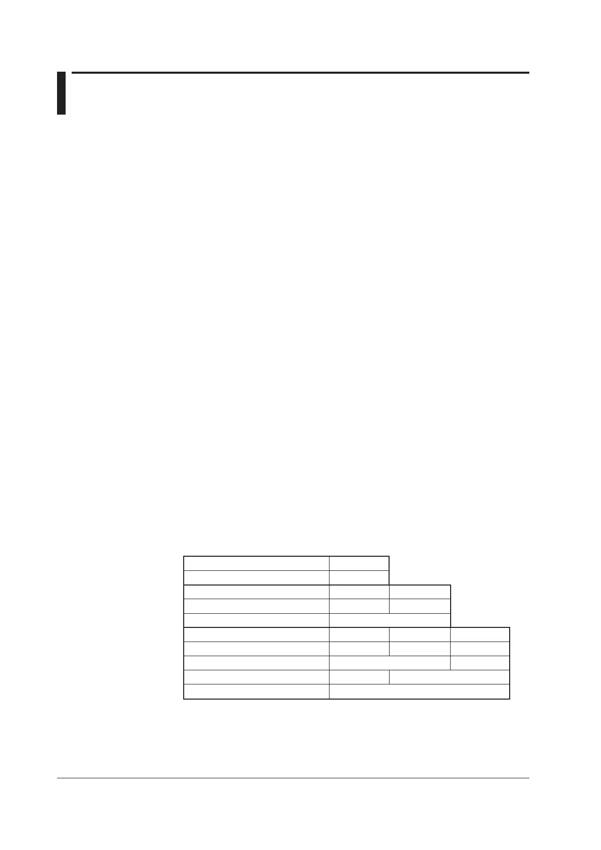
• The following table shows the relationship between the number of installed input
elements, the selectable wiring system patterns, and the assignment of input elements
to wiring unit
Σ
.
For example, there are four wiring system patterns on a WT50
0 that has three input
elements installed.
•
The input element assignment to wiring unit
Σ
and how
Σ
functions (such as voltage,
current, active power, apparent power, reactive power, power factor, and phase
difference) are determined are based on the wiring system pattern. For details about
the relationship between the wiring system and how
Σ
functions data is determined,
see Appendix 1.
Number of installed input elements
Wiring system Pattern 1
1
1P2W
Number of installed input elements
Wiring system Pattern 1
Wiring system Pattern 2
1
1P2W
2
1P2W
1P3W:3 or 3P3W:3
Number of installed input elements
Wiring system Pattern 1
Wiring system Pattern 2
Wiring system Pattern 3
Wiring system Pattern 4
1
1P2W
2
1P2W
3
1P2W
1P2W
1P2W
1P3W:3 or 3P3W:3
1P3W:3 or 3P3W:3
3P4W:3 or 3P3W (3V3A):3

 Loading...


