2-9
IM 760201-01E
Features
3
2
1
4
5
6
7
8
9
10
11
12
13
14
App
Index
Measurement Period (See section 4.7 for operating instructions)
Measurement Functions Used in Normal Measurement
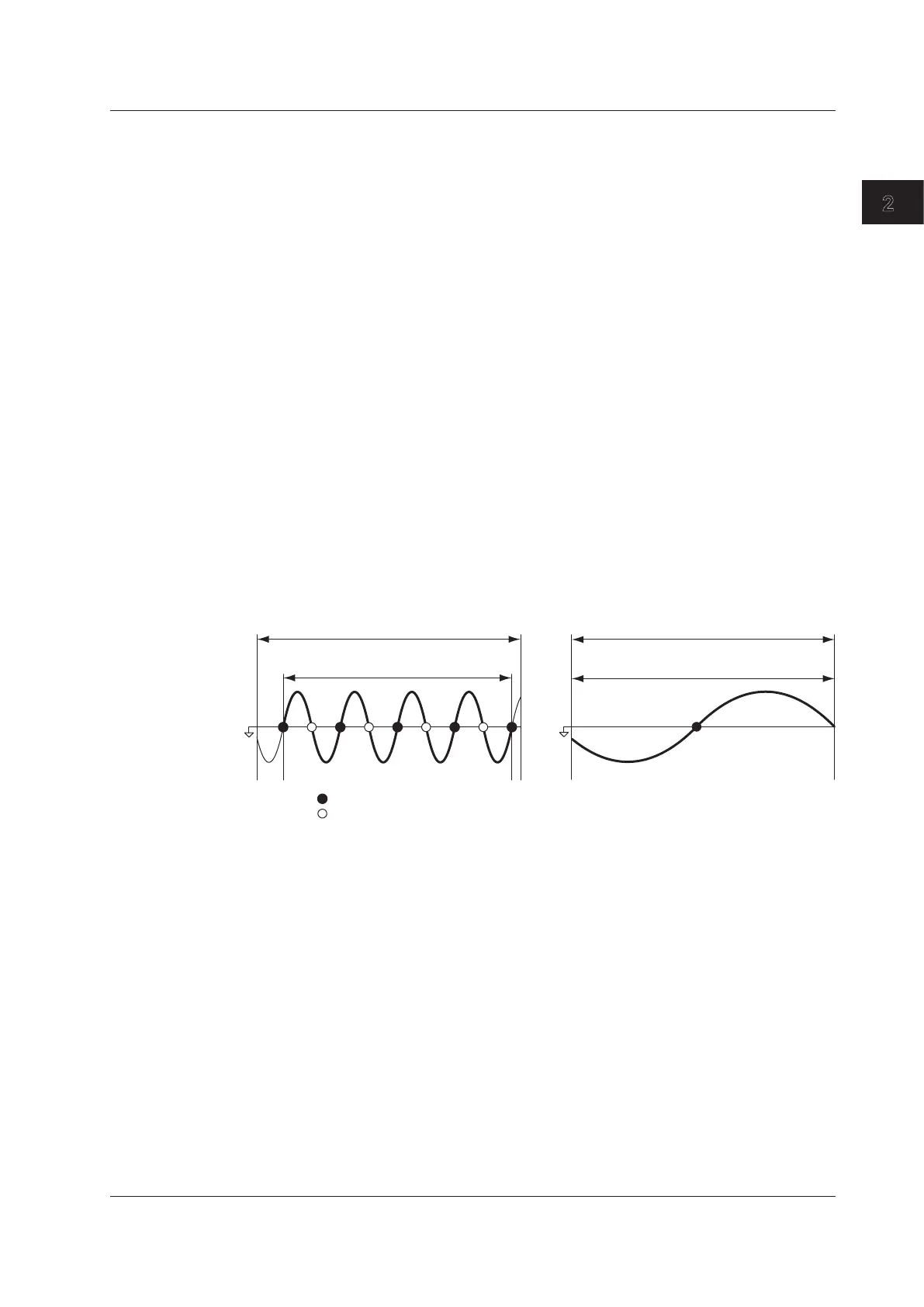
• The measurement period is set within the data update interval between the first point
where the reference input signal (synchronization source) crosses the level zero point
(center of the amplitude) on the rising trigger slope (or falling trigger slope) and the
last point where the synchronization source crosses the level zero point (center of the
amplitude) on the rising slope (or falling slope).
1, 2
However, the measurement period
for determining the numeric data of the peak voltage or peak current is the entire span
of the data update interval. Therefore, the measurement period for the measurement
functions that are determined using the maximum voltage or current value (U+pk,
U-pk, I+pk, I-pk, CfU, and CfI) is also the entire span of the data update interval.
•
The WT500 determines whether to define the measurement period using the rising
or falling edge automatically by choosing the method that will result in the longest
measurement period.
•
If there is not more than one rising or falling slope within the data update interval, the
entire data update interval is set as the measurement period.
•
You can select which input signal will be the synchronization source (synchronized
to the zero-crossing point of the input signal) for each element. You can set the
synchronization source signal to the voltage, current, or external clock input signal.
•
For details, see appendix 6.
1 Trigger slope refers to the movement of the signal from a low level to a high level (rising edge)
or from a high level to a low level (falling edge).
2 The data update interval is the interval at which the data that is used in measurement
functions is sampled. For details on how to set the interval, see section 2.3, “Data Update
Rate.”
Data update interval
Measurement period
Sync source
zero crossing
zero crossing
Data update interval
Measurement period
Measurement Functions Used in Harmonic Measurement
The measurement period is the first 1024 points from the beginning of the data update
interval at the harmonic sampling frequency. The WT500 determines the harmonic
sampling frequency automatically based on the period of the signal that is set as the PLL
source. The sampled data and the measurement period used for computation may differ
from the sampled data and the measurement period used for measurement functions.
2.2 Measurement Functions and Periods

 Loading...


