1-1
IM 760201-01E
Component Names and Functions
3
2
1
4
5
6
7
8
9
10
11
12
13
14
App
Index
Chapter 1 Component Names and Functions
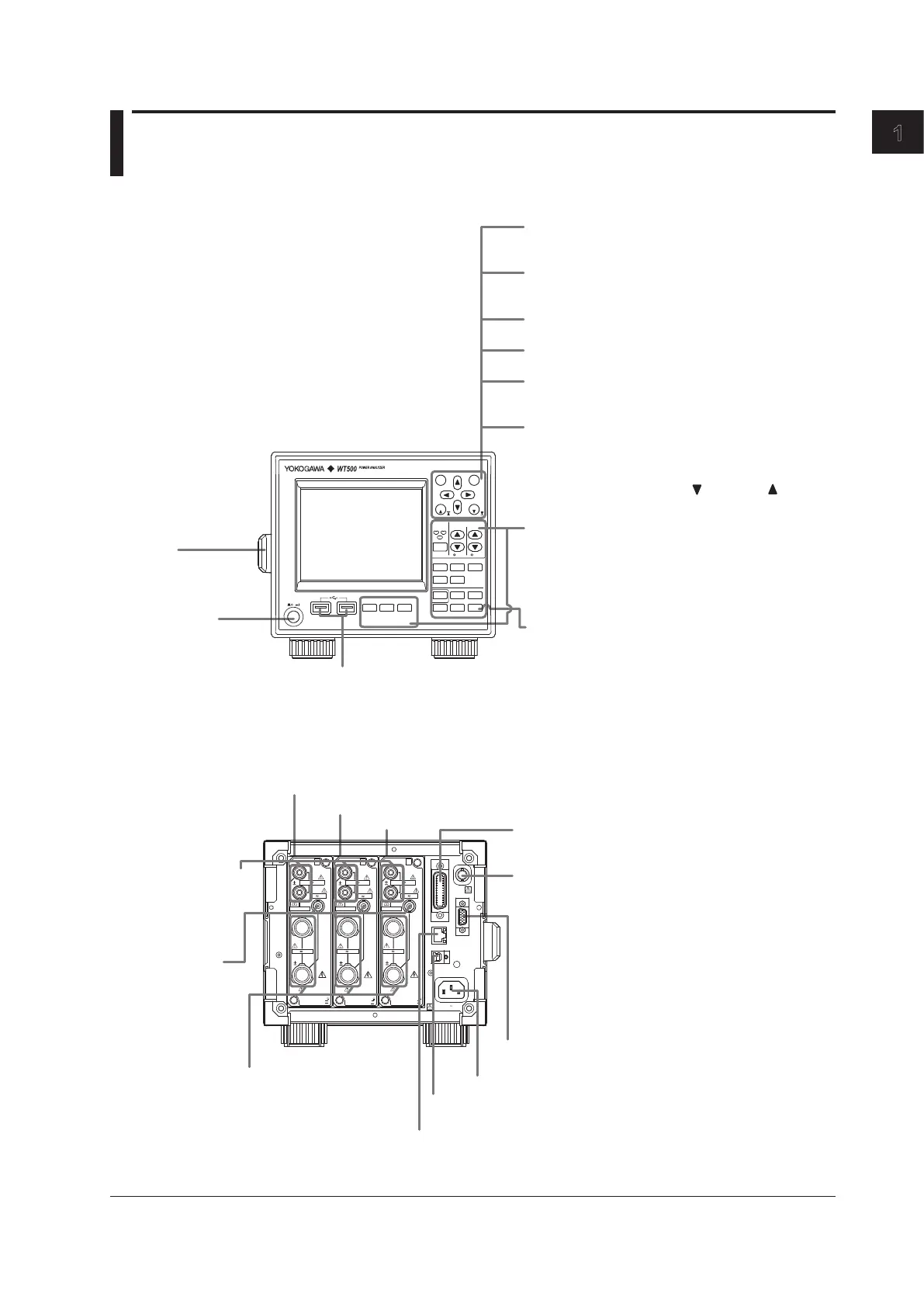
1.1 Front Panel, Rear Panel, and Top Panel
Front Panel
Power switch
(see section 3.4)
LCD
Handle
Use this handle to
move the WT500.
(see section 3.1)
Setup menu display and operation keys
These are the first keys that you press when you make
settings or perform operations. Pressing a setup menu
display key will display its corresponding setup menu.
Pressing an operation key will execute its
corresponding operation. (see section 1.2)
SHIFT key
When you press the SHIFT key, the key illuminates,
and pressing a panel keys produces the effect
indicated by the purple letters below it.
USB ports
Use to connect USB memory
or a USB keyboard.
ESC
RESET
SET
CAL
PAGE
PAGE
ELEMENT
1
2
3
ELE MENT
ALL
RANGE
VOLTAGE CURRENT
AUTO AUTO
DISPLAY
NUM ERIC WAVE OTH ERS
FOR M ITEM
CUR SOR
INTEG RATOR
SET UP
INPU T INFO
START /
STOP
RESE T
HOL D
SING LE
SHI FT
MIS C
NULL
LOC AL
KEY LOCK
FIL E IMAG E
MENU
STOR E
STOR E SET
POW ER
Cursor keys
Set values (and select digits), move the cursor, and
select items in setup operations.
SET key
Enters or confirms the item or value selected using the
cursor keys.
SHIFT + SET (CAL) key combination
Executes zero-level compensation.
ESC key
Closes setup menus and dialog boxes.
SHIFT + ESC (RESET) key combination
Returns the item or value selected with the cursor to its
default value.
PAGE key
Because not all measured items can be displayed
on the screen at the same time, the WT500 uses
pages to display measured values. You can switch
between pages using PAGE and PAGE .
(see section 5.1)
Rear Panel
Input element 1
(see section 2.3)
Input element 2
Input element 3
Ethernet port (optional) (see section 11.2)
Power connector (see section 3.3)
USB port (PC) See the Communication Interface User’s Manual
IM760201-17E (CD-ROM).
External clock input/External start signal output
connector
• Receives the synchronization source (signal), which
defines the measurement period. (see section 4.7)
• Receives the external PLL source (signal) for
harmonic measurement. (see section 6.3)
• Used when performing master/slave synchronized
measurement.(see section 12.6)
• Receives the external trigger, which determines when
a waveform is displayed. (see section 7.5)
GP-IB Connector (optional; see the Communication
Interface User's Manual IM760201-17E on the
CD-ROM)
RGB video signal (VGA) output connector (optional)
Transmits image signals. (see section 12.2)
Current input terminal
For connecting current
measurement cables.
(see sections 3.8, 3.9,
and 3.11)
External current
sensor input
connector (optional)
For connecting the
external current
sensor cable.
(see section 3.10)
Voltage input terminal
For connecting voltage
measurement cables.
(see sections
3.8 to 3.11)
EL EMENT
VOLTAG E
100 0V
MAX
EXT
CUR REN T
ALL TERM INA LS
1000V MA X
TO
CAT
II
EXT. C LK
GP- IB
(
IEE E 488
)
LIN K/
ACT
VID EO-OUT
(
VGA
)
100 -
LIN K
ETH ERNE T 10 0BAS E-TX
USB
10 0-2 40 V A C
50 VA M AX 5 0/60 H z
10V
MAX
100 0VM AX
40A
MAX
EL EMENT
VOLTAG E
100 0V
MAX
EXT
CUR REN T
ALL TERM INA LS
1000V MA X
TO
CAT
II
10V
MAX
100 0VM AX
40A
MAX
EL EMENT
VOLTAG E
100 0V
MAX
EXT
CUR REN T
ALL TERM INA LS
1000V MA X
TO
CAT
II
10V
MAX
100 0VM AX
40A
MAX

 Loading...


