2-2
IM 760201-01E
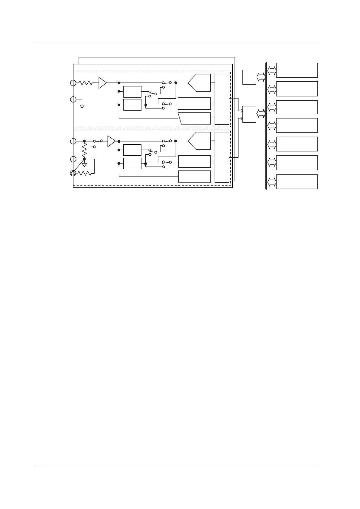
Block Diagram
U
±
L.P.F.
5.5 kHz
L.P.F.
500 Hz
L.P.F.
5.5 kHz
L.P.F.
500 Hz
A/D
Isolator Isolator
Zero-crossing
detector
Peak
detector
I
±
Current sensor
(EXT; optional)
Voltage input circuit
Current input circuit
Input element 1
Input elements 2 and 3
DSP
CPU
LCD
USB port
(for peripherals)
USB port
(PC)
GP-IB
(optional)
Ethernet
(optional)
VGA output
(optional)
KEY
Voltage Input
Current input
A/D
Zero-crossing
detector
Peak
detector
Input Signal Flow and Process
Input elements 1 through 3 consist of a voltage input circuit and a current input circuit.
The input circuits are mutually isolated. They are also isolated from the case.
The voltage signal that is applied to the voltage input terminal (U, ±) is normalized using
the voltage divider and the operational amplifier (op-amp) of the voltage input circuit . It is
then sent to a voltage A/D converter.
The current input circuit is equipped with two types of input terminals, a current input
terminal (I, ±) and an optional current sensor input connector (EXT). Only one can be
used at any given time. The voltage signal from the current sensor that is received at the
current sensor input connector is normalized using the voltage divider and the operational
amplifier (op-amp). It is then sent to a current A/D converter. The current signal that is
applied to the current input terminal is converted to a voltage signal by a shunt. Then, it
is sent to the current A/D converter in the same fashion as the voltage signal from the
current sensor.
The voltage signal that is applied to the voltage A/D converter and current A/D converter
is converted to digital values at an interval of approximately 10
µ
s. These digital values
are isolated by the isolator and passed to the DSP. In the DSP, the measured values
are derived based on the digital values. The measured values are then transmitted to
the CPU. The measured values and computed values are displayed and transmitted as
measurement functions of normal measurement.
The harmonic measurement functions are derived in the following manner (harmonic
measurement is an option). The voltage signal sent to the A/D converter is converted to
digital values at a sampling frequency that is determined by the PLL source signal. The
DSP derives the measured value of each harmonic measurement item by performing an
FFT on the converted digital values.
2.1 System Configuration and Block Diagram

 Loading...


