3-15
IM 760201-01E
Before You Start Measuring
3
2
1
4
5
6
7
8
9
10
11
12
13
14
App
Index
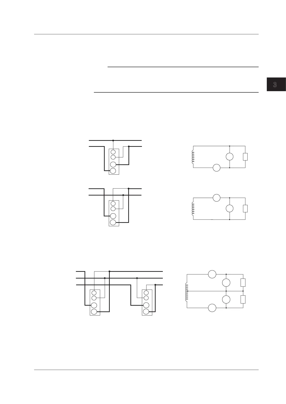
The assignment of elements to the input terminals in the wiring example figures below
varies depending on the number of installed input elements. For details, see “Number of
Installed Input Elements and Wiring Systems” in section 2.3, “Measurement Conditions.”
Note
• After you have finished wiring, you must select the wiring system. For details, see section 4.2,
“Selecting the Wiring System.”
• The thick lines on the wiring diagrams are the sections where the current flows. Use wires
that are suitable for the current levels.
Single-Phase, Two-Wire System Wiring Example (Applicable for models 760201,
760202, and 760203)
If three input elements are available, three single-phase, two-wire systems can be set up.
See section 3.7 for information about which of the wiring systems shown below should
be selected.
SOURCE
LOAD
U1
I1
I
U
LOAD
U1
U
I1
I
SOURCE
SOURCE
LOAD
Input terminal
SOURCE
LOAD
Input terminal
I
U
I
U
±
!pm!
±
±
±
±
±
±
Single-Phase, Three-Wire System Wiring Example (Applicable for models 760202
and 760203)
If three input elements are available, two single-phase, three-wire systems can be set up
(elements 1 and 2, or elements 2 and 3).
SOURCE
LOAD
N
N
SOURCE
Input terminal 1
LOAD
Input terminal 2
I
I
U
U
I2
I1
U1
U2
I
U
I
U
±
±
±
±
±
±
±
±
3.9 Wiring the Circuit That You Will Measure for Direct Input

 Loading...


