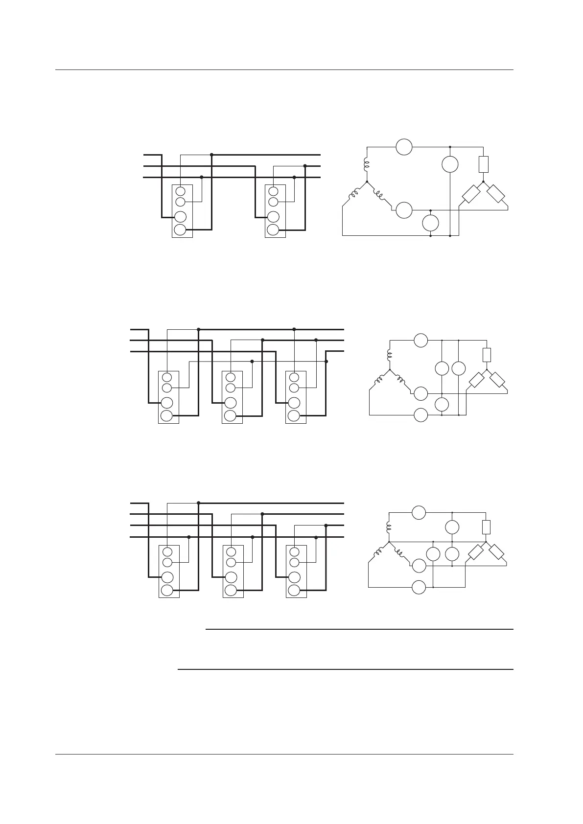
Three-Phase, Three-Wire System Wiring Example (Applicable for models 760202
and 760203)
If three input elements are available, two three-phase, three-wire systems can be set up
(elements 1 and 2, or elements 2 and 3).
R
ST
SOURCE
LOAD
SOURCE
Input terminal 1
LOAD
Input terminal 2
I1
I2
U1
U2
I
I
U
U
R
S
T
I
U
I
U
±
±
±
±
±
±
±
±
Wiring Example of a Three-Phase, Three-Wire System with a Three-Voltage,
Three-Current Method (3P3W; 3V3A) (Applicable for model 760203)
If three input elements are available, one three-phase, three-wire system with a three-
voltage, three-current method can be set up (elements 1, 2, and 3).
SOURCE
LOAD
I
I
R
S
T
U
U
U
I
SOURCE
Input terminal 1
LOAD
Input terminal 2
R
S
T
I1
I2
I3
U3 U1
U2
Input terminal 3
I
U
I
U
I
U
±
±
±
±
±
±
±
±
±
±
±±
Three-Phase, Four-Wire System Wiring Example (Applicable for model 760203)
If three input elements are available, one three-phase, four-wire system can be set up
(elements 1, 2, and 3).
SOURCE
LOAD
I
I
R
ST
U
U
U
I
N
SOURCE
Input terminal 1
LOAD
Input terminal
2
R
S
T
N
I1
I2
I3
U1
U2U3
Input terminal 3
I
U
I
U
I
U
±
±
±
±
±
±
±
±
±±
±
±
Note
For details about the relationship between the wiring system and how measured and
computed values are determined, see appendix 1, “Symbols and Determination of
Measurement Functions.”
3.9 Wiring the Circuit That You Will Measure for Direct Input

 Loading...


