1.2 Setup Menu Display and Operation Keys
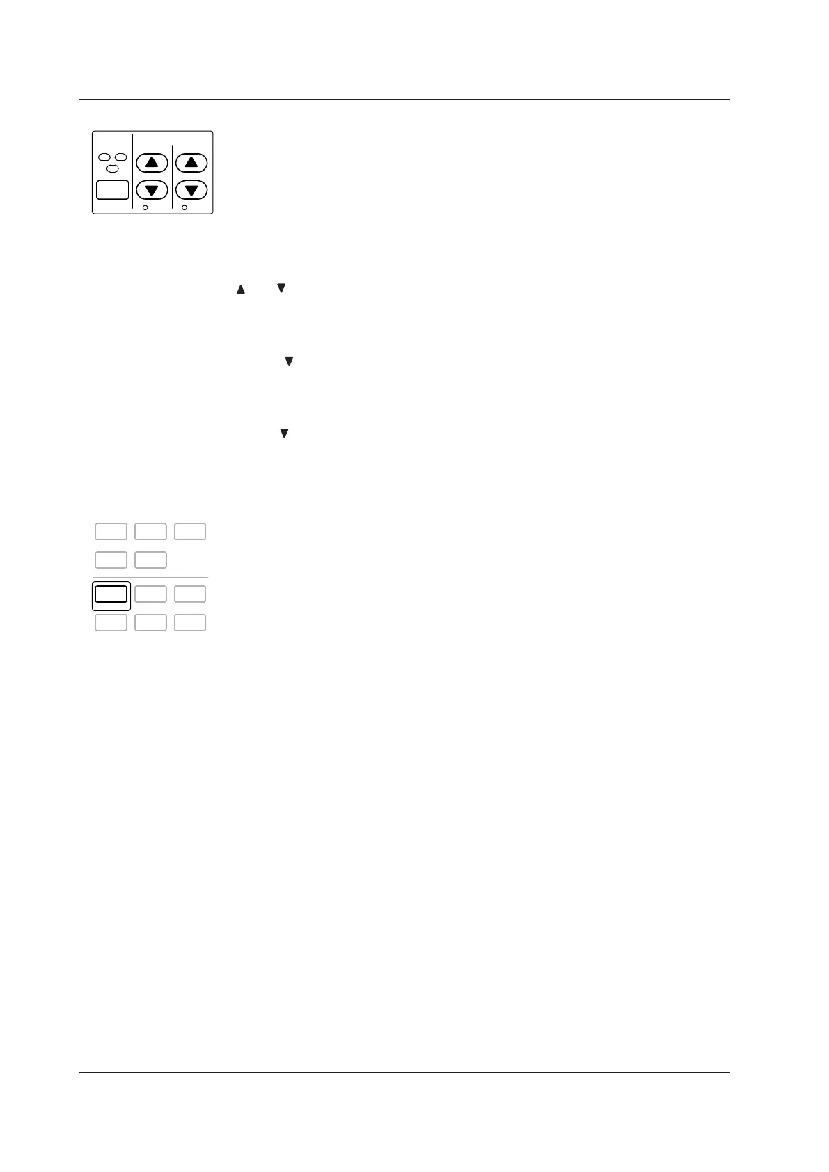
Keys for Setting the Measurement Range
ELEMENT
1
2
3
E LEMENT
ALL
RANGE
VOLTAGE CURRENT
AUTO AUTO
ELEMENT
• Use this key to select the input element that you want to set the measurement range
for. The selected input element will change each time you press ELEMENT.
•
When selecting a wiring system, the input elements that are part of the same wiring
system will be selected together.
SHIFT+ELEMENT (ALL) Key Combination
Use this key combination to set the voltage and current ranges of all elements at the
same time. Press ELEMENT again to make settings for individual elements.
and (See sections 4.3 and 4.4)
Use these keys to select the voltage, current, and current sensor ranges. The ranges
selected with these keys are valid when the AUTO indicators described below are not
lighted (when the manual range feature is being used).
SHIFT+ (AUTO) Key Combination
Use this key combination to activate the auto range feature (the AUTO indicator will light
when this feature is activated). This feature automatically sets the voltage, current, or
current sensor range depending on the amplitude of the received electrical signal. Press
SHIFT+
(AUTO) again to activate the manual range feature (the AUTO indicator light
will turn off).
Keys for Setting Measurement Conditions
SETUP
INPUT INFO
DISPLAY
NUMERIC WAVE OTHERS
FORM ITEM
CURSOR
INTEGRATOR
START/
STOP
RESET
HOLD
SINGLE
SHIFT
MISC
NULL
LOCAL
KEY LOCK
SETUP
Use this key to display the Setup menu for setting measurement conditions. The following
items appear in the Setup menu:
• Wiring (See sections 4.1, 4.2, 5.7, and 5.8)
Select this item to display a menu for selecting the wiring system, configuring
individual input element settings, setting the efficiency equation, etc.
• Ranges (See sections 4.3 and 4.4)
You can select this item to set the voltage, current, or current sensor range, just as
you can with the panel RANGE keys. If you select AUTO, the auto feature will be
activated and the AUTO indicators underneath the RANGE keys will light.
• Scaling (See section 4.5)
Select this item to display a menu for setting the VT and CT ratios and the power
factor for each input element. The power coefficients are used to convert the VT/CT
output or the power derived from measuring the VT and CT outputs to the voltage,
current, and power of the object being measured.
• Sync Source (See section 4.7)
Select this item to display a menu for setting the synchronization source for each
wiring unit. The synchronization source defines the period (measurement period) over
which sampled data, which is used to produce numeric data (i.e., measured values
such as voltage, current, and power), is acquired.
• Filters (See section 4.8)
Select this item to display a menu for setting the line filter (which is inserted into the
measurement circuit) and the frequency filter (which is inserted into the frequency
measurement circuit) for each element.
• Update Rate (See section 4.9)
Select this item to display a menu for selecting the period (data update rate) at which
sampled data, which is used to produce numeric data (i.e., measured values such as
voltage, current, and power), is acquired.
• Averaging (See section 4.10)
Select this item to display a menu for setting the measured value averaging feature.

 Loading...


