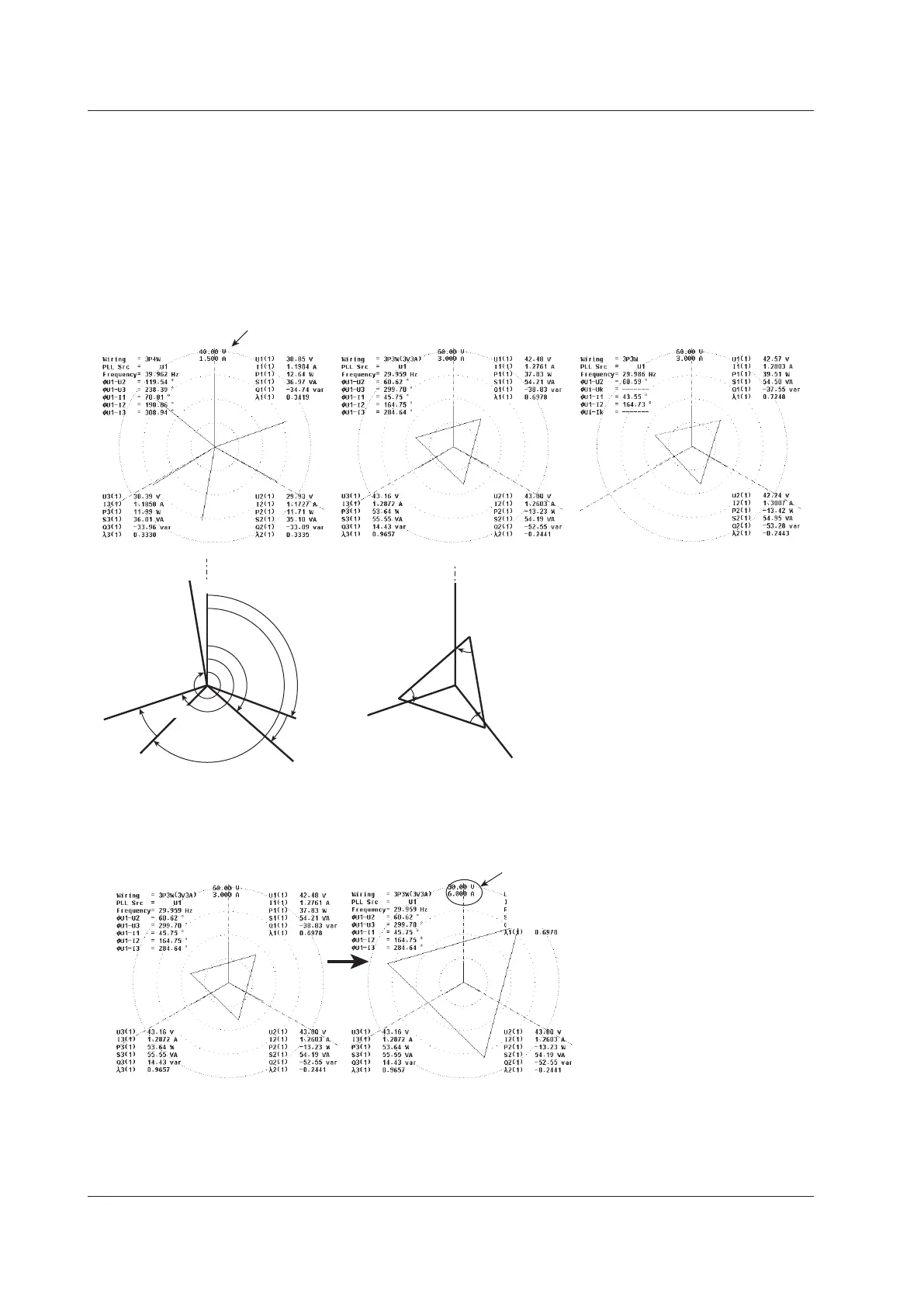
When Displaying Numeric Data
(of the sizes of the signals and the phase differences between signals)
When the vector size is zoomed
For a 3P4W
(three-phase, four-wire system)
• U1(1), U2(1), and U3(1) are
line voltages.
• I1(1), I2(1), and I3(1) are
line currents.
For a 3P3W system with
a three-voltage, three-current method
• U1(1), U2(1), and U3(1) are
line voltages.
• I1(1), I2(1), and I3(1) are line
currents.
For a 3P3W
(three-phase, three-wire system)
• U1(1), U2(1), and U3(1) are line
voltages.
• I1(1), I2(1), and I3(1) are line
currents.
However, U3(1) and I3(1) are not
actually
measured for the 3P3W system.
The vectors
are displayed through computation.
φ2(1)
φ1(1),
φU1-I1
φ3(1)
φU1-U3
φU1-I2
U1(1)
I1(1)
I3(1)
U3(1)
I2(1)
U2(1)
φU1-U2
φU1-I3
I1(1)
I3(1)
I2(1)
O
U1(1)
U3(1)
U2(1)
φU1-U2
φU2-U3
φU3-U1
• By moving the vectors U1(1), U2(1), and
U3(1) so that the starting points of all
vectors are at the origin O, the phase
relationship can be observed in the same
fashion as the 3P4W system. For
information about the relationship between
the positions of the vectors after they have
been moved, see "Vector Display of
Harmonic Data" in section 7.1. (The WT500
does not provide a function for moving the
vectors.)
• The phase difference between the line
voltages can be determined from the phase
difference measurement functions φU1 - U2
and φU1-U3.
φU1 - U2 = Measurement function φU1 - U2
φU2 - U3 = (φU1-U3) – (φU1 - U2) – 180
φU3 - U1 = – (φU1-U3)
Size of the peripheral circle (range)
Example in which the voltage is zoomed
by a factor of 2 and the current by a factor of 1/2
The value of the size of the peripheral circle
(range)
The sizes of the vectors representing
voltage and current are multiplied 2 times
and 1/2 times, respectively.

 Loading...


