App-3
IM 760201-01E
Appendix
3
2
1
4
5
6
7
8
9
10
11
12
13
14
App
Index
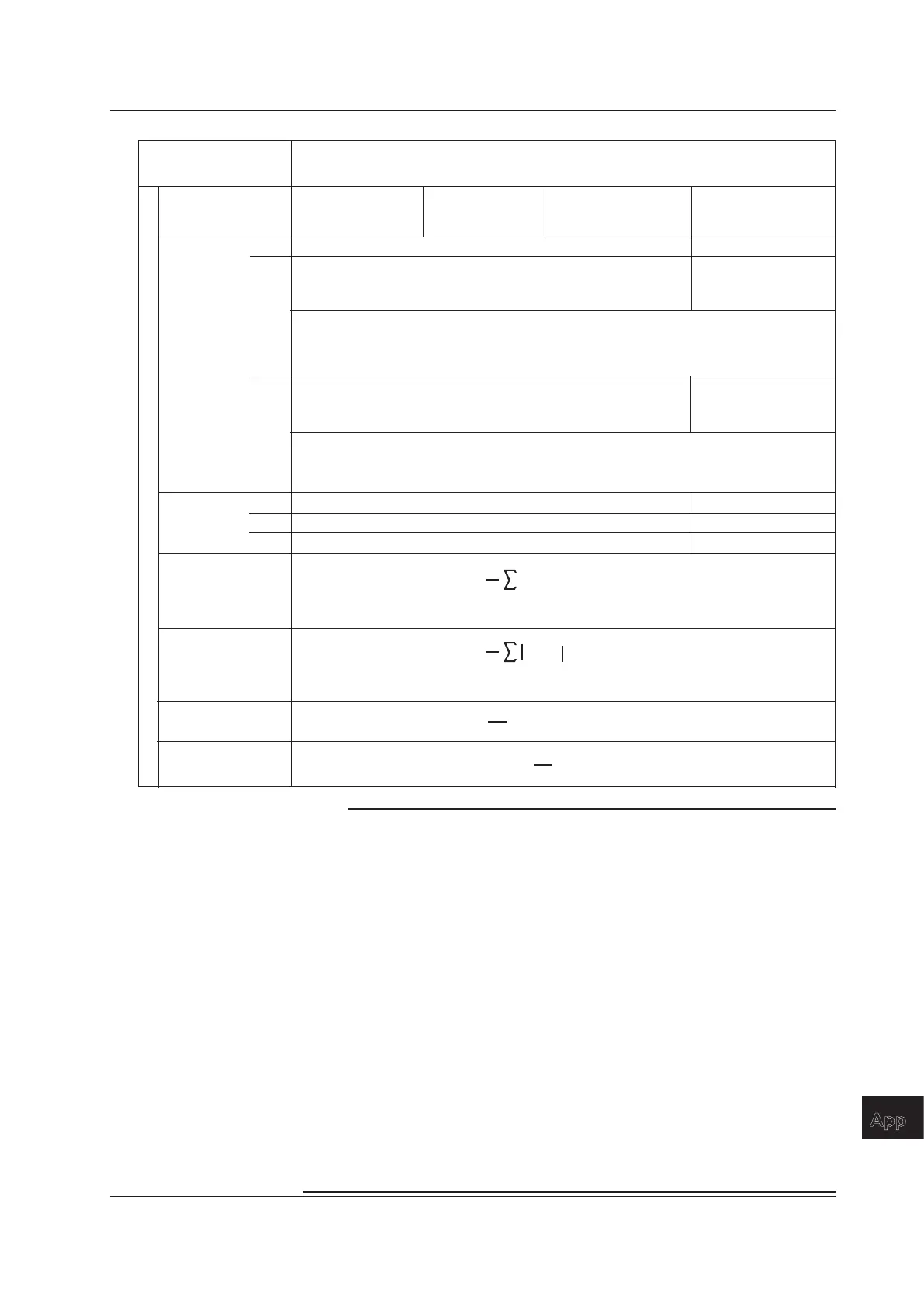
Measurement Functions
Used in Normal
Measurement
Methods of Computation and Determination
For information about the symbols in the equations see the notes.
(Table 3/3)
Single-phase,
three-wire
1P3W
Three-phase,
three-wire
3P3W
Three-phase, three-wire with
three-voltage, three-current
method.
3P3W(3V3A)
Three-phase,
four-wire
3P4W
Wiring system
WP
3
[Wh]
WP
3
WP1 + WP2 WP1 + WP2 + WP3
WS3
[VAh]
WQ
3
[varh]
S3(n) is the nth apparent power 3 function. N is the number of data updates.
The unit of time is hours.
S
3
(n) • Time
n = 1
N
Q
3
(n) • Time
n = 1
N
Q3(n) is the nth reactive power 3 function. N is the number of data updates.
The unit of time is hours.
1
N
1
N
P
3
S
3
L
3
3functions
WP+
3
WP–
3
WP+1 + WP+2
When the watt-hour integration method for each polarity is
Charge/Discharge
WP+1 + WP+2 + WP+3
WP+
3
is the sum of the positive active power WPS values at each data
update interval.
When the watt-hour integration method for each polarity is Sold/Bought
WP–1 + WP–2
WP–1 + WP–2 + WP–3
When the watt-hour integration method for each polarity is
Charge/Discharge
WP-
3
is the sum of the negative active power WPS values at each data
update interval.
When the watt-hour integration method for each polarity is Sold/Bought
q
3
[Ah]
q
3
q+
3
q–
3
q1 + q2
q+1 + q+2
q–1 + q–2
q1 + q2 + q3
q+1 + q+2 + q+3
q–1 + q–2 + q–3
COS
-1
(
)
P
3
S
3
F
3
[°]
Note
• u(n) denotes the instantaneous voltage. i(n) denotes the instantaneous current.
• n denotes the n
th
measurement period. The measurement period is determined by the
synchronization source setting.
• AVG[ ] denotes the simple average of the item in brackets determined over the data
measurement interval. The data measurement interval is determined by the synchronization
source setting.
• P
Σ
denotes the active power of wiring unit
Σ
. Input elements are assigned to wiring unit
Σ
differently depending on the number of input elements that are installed in the WT500 and
the selected wiring system pattern. For details, see section 2.3.
• The numbers 1, 2, and 3 used in the equations for Urms
Σ
, Umn
Σ
, Urmn
Σ
, Udc
Σ
, Uac
Σ
,
Irms
Σ
, Imn
Σ
, Irmn
Σ
, Idc
Σ
, Iac
Σ
, P
Σ
, S
Σ
, Q
Σ
, WP
Σ
, and q
Σ
indicate the case when input
elements 1, 2, and 3 are set to the wiring system shown in the table.
• Equation Type 3 for S
Σ
and Q
Σ
can only be selected on models with the harmonic
measurement option.
• On the WT500, S, Q,
λ
, and
f
are derived through the computation of the measured values
of voltage, current, and active power (however, when Type 3 is selected, Q is calculated
directly from the sampled data). Therefore, for distorted signal input, the value obtained on
the WT500 may differ from that obtained on other instruments that use a different method.
• For Q [var], when the current leads the voltage, the Q value is displayed as a negative
value; when the current lags the voltage, the Q value is displayed as a positive value. The
value of Q
Σ
may be negative, because it is calculated from the Q of each element with the
signs included.
Appendix 1 Symbols and Determination of Measurement Functions

 Loading...


