App-5
IM 760201-01E
Appendix
3
2
1
4
5
6
7
8
9
10
11
12
13
14
App
Index
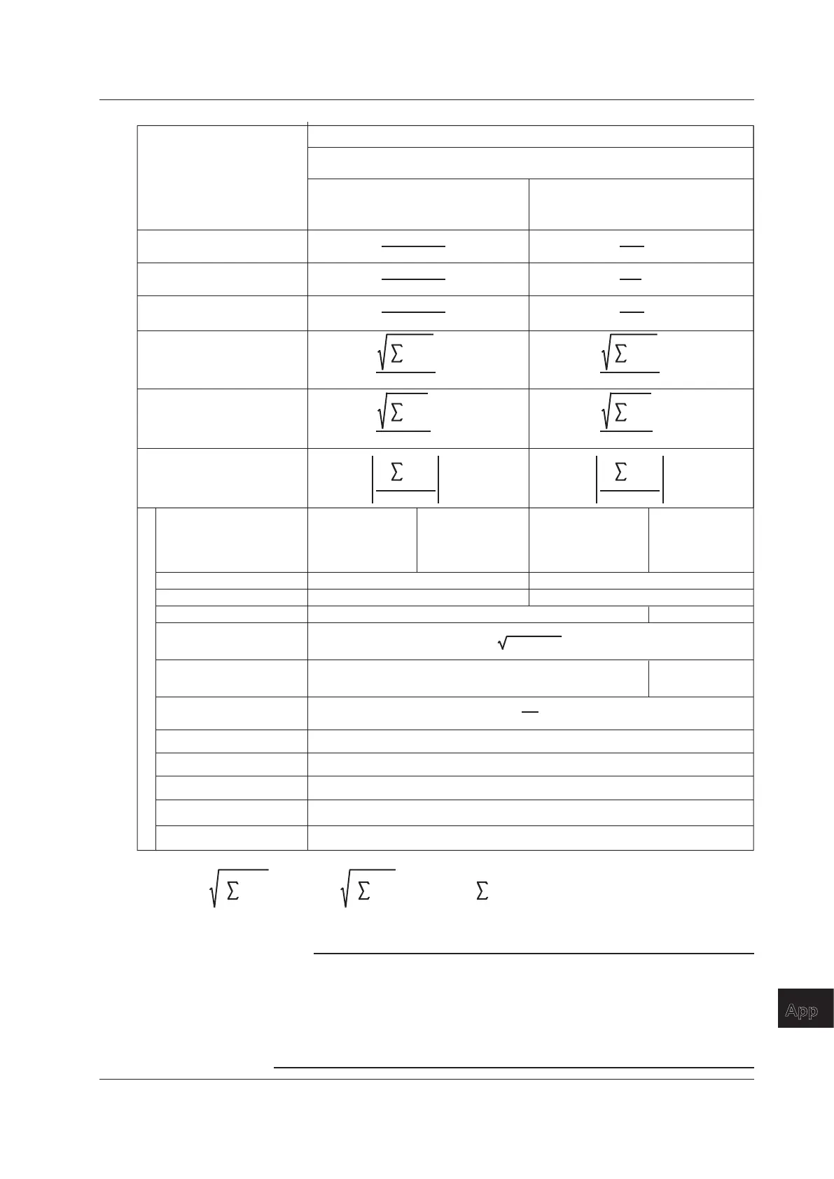
Harmonic voltage distortion
factor Uhdf( ) [%]
Total harmonic
voltage distortion
Uthd [%]
The numbers and characters in the parentheses are dc (when k = 0),
or k (when k = 1 to max).
Measurement Functions
Used in Harmonic
Measurement
Methods of Computation and Determination
(Table 2/2)
U(k)
U(Total)
*1
U(k)
U(1)
• 100 • 100
P(k)
P(Total)
*1
P(k)
P(1)
• 100 • 100
I(k)
I(Total)
*1
I(k)
I(1)
• 100 • 100
Harmonic active power
distortion factor Phdf( ) [%]
Harmonic current distortion
factor Ihdf( ) [%]
k = 2
max
U(k)
2
U(Total)
*1
•
100
k = 2
max
U(k)
2
U(1)
• 100
Total harmonic active power
distortion Pthd [%]
k = 2
max
P(k)
P(Total)
*1
•
100
k = 2
max
P(k)
P(1)
• 100
Total harmonic current
distortion Ithd [%]
k = 2
max
I(k)
2
I(Total)
*1
•
100
k = 2
max
I(k)
2
I(1)
• 100
When the denominator of the
distortion factor is the
total value (Total)
When the denominator of the
distortion factor is the
fundamental signal (Fundamental)
Three-voltage,
three-current
method (3V3A)
P1 + P2 + P3PΣ [W] P1 + P2
UΣ [V]
IΣ [A]
(U1 + U2) / 2
(I1 + I2) / 2
(U1 + U2 + U3) / 3
(I1 + I2 + I3) / 3
PΣ
2
+ QΣ
2
SΣ [VA]
Q1 + Q2
QΣ [var]
Q1 + Q2 + Q3
PΣ
SΣ
λΣ
(TYPE3)
*2
(TYPE3)
*2
φU1-U2(°) Phase difference between U1(1) and the fundamental voltage of element 2, U2(1)
φU1-U3(°) Phase difference between U1(1) and the fundamental voltage of element 3, U3(1)
φU1-I1(°) Phase difference between U1(1) and the fundamental current of element 1, I1(1)
φU1-I2(°) Phase difference between U1(1) and the fundamental current of element 2, I2(1)
φU1-I3(°) Phase difference between U1(1) and the fundamental current of element 3, I3(1)
Single-phase,
three-wire
1P3W
Three-phase,
three-wire
3P3W
Three-phase,
four-wire
3P4W
Wiring system
Σ function
*1
U(k)
2
k = min
max
U(Total) =
I(k)
2
P(k)
k = min
max
I(Total) =,
k = min
max
P(Total) =,
*2 For details about the S
Σ
and Q
Σ
formula type settings, see section 5.4.
Note
• k denotes a harmonic order, r denotes the real part, and j denotes the imaginary part.
• The minimum harmonic order is denoted by min.
• The upper limit of harmonic analysis is denoted by max. max is determined automatically
according to the PLL source frequency. It can go up to the 50
th
harmonic order.
• The numbers 1, 2, and 3 used in the equations for U
Σ
, I
Σ
, P
Σ
, S
Σ
, and Q
Σ
indicate the case
when input elements 1, 2, and 3 are set to the wiring system shown in the table.
• Only the total value and the fundamental signal (1
st
harmonic) are computed for
Σ
.
Appendix 1 Symbols and Determination of Measurement Functions

 Loading...


