App-20
IM 760201-01E
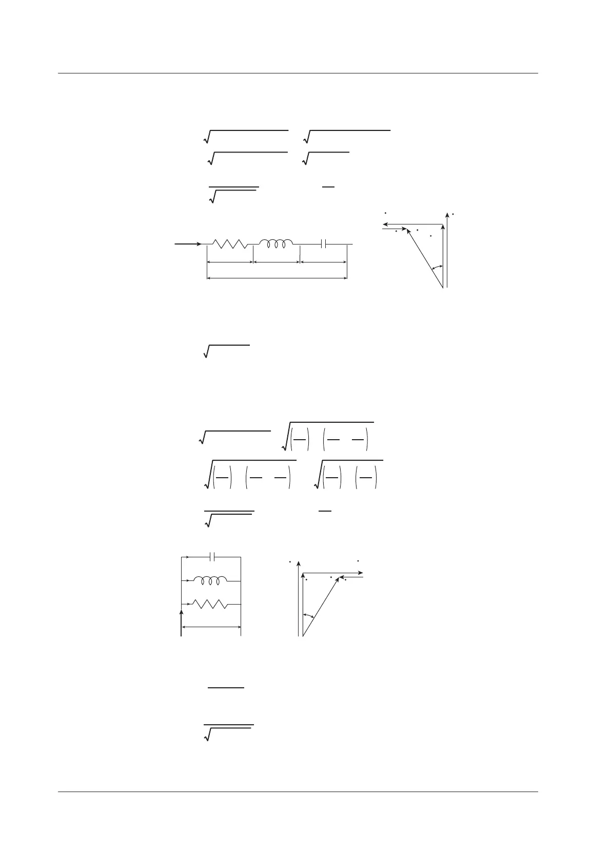
Series RLC Circuits
The equation below expresses the voltage relationships when resistance R
S
[
Ω
],
inductance L [H], and capacitance C [F] are connected in series.
U = (URS)
2
+ (UL – UC)
2
=
(IRS)
2
+ (IXL – IXC)
2
=
I (RS)
2
+ (XL – XC)
2
=
I RS
2
+ XS
2
I
=
U
RS
2
+ XS
2
, φ
=
tan
–1
XS
RS
The relationship between resistance R
S
, reactance X
S
, and impedance Z is expressed by
the equations below.
Parallel RLC Circuits
The equation below expresses the current relationships when resistance R
P
[
Ω
],
inductance L [H], and capacitance C [F] are connected in parallel.
I= (IRP)
2
+ (IL–IC)
2
=
U
=
IRPXP
RP
2
+ XP
2
, φ
= tan
–1
RP
XP
RP
U
2
+
XL
U
–
XC
U
2
=
RP
1
2
+
XL
1
–
XC
1
2
U
=
RP
1
2
+
XP
1
2
U
The relationship between resistance R
P
, reactance X
P
, and impedance Z is expressed by
the equations below.
Z =
RPXP
RP
2
+ XP
2
XP =
XLXC
XC – XL
Appendix 3 Power Basics (Power, harmonics, and AC RLC circuits)

 Loading...


