App-22
IM 760201-01E
Effects of Stray Capacitance
The effects of stray capacitance on measurement accuracy can be minimized by
connecting the WT500 current input terminal to the side that is closest to the earth
potential of the power source (SOURCE).
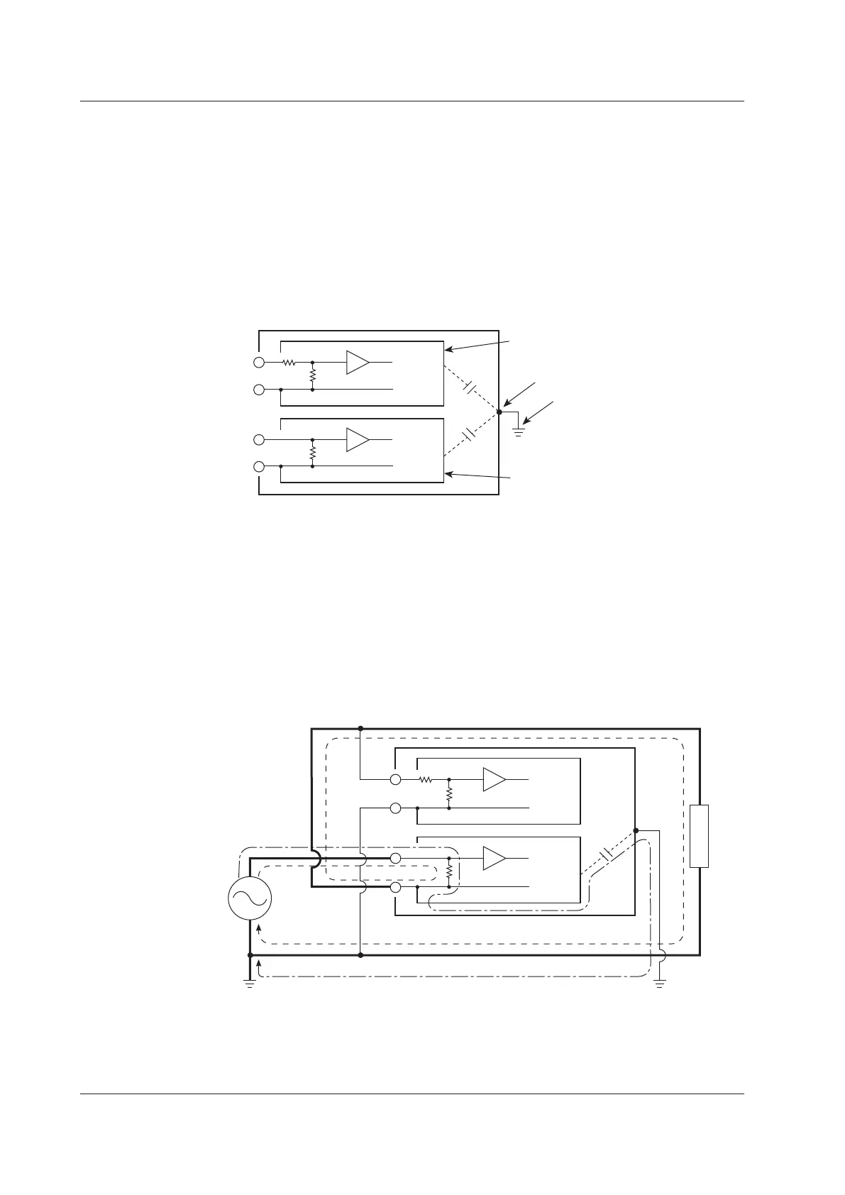
The internal structure of the WT500 is as follows:
The voltage and current measurement circuits are each enclosed in shielded cases.
These shielded cases are contained within an outer case. The shielded case of the
voltage measurement circuit is connected to the positive and negative voltage input
terminals, and the shielded case of the current measurement circuit is connected to the
positive and negative current input terminals.
Because the outer case is insulated from the shielded cases, there is stray capacitance,
which is expressed as Cs. Cs is approximately 100 pF. The current generated by stray
capacitance Cs causes errors.
U
I
Cs
Cs
Shielded case of the voltage
measurement circuit
Outer case
Grounding
Shielded case of the current
measurement circuit
±
±
As an example, we will consider the case when the outer case and one side of the power
source are grounded.
In this case, there are two conceivable current flows, load current i
L
and the current that
flows through the stray capacitance i
Cs
. i
L
flows through the current measurement circuit,
then through the load, and returns to the power source (shown with a dotted line). i
Cs
flows through the current measurement source, the stray capacitance, and the earth
ground of the outer case, and then returns to the power source (shown with a dot-dash
line).
Therefore, the current measurement circuit ends up measuring the sum of i
L
and i
Cs
,
even if the objective is just to measure i
L
. Only i
Cs
reduces measurement accuracy. If the
voltage applied to Cs is V
Cs
(common mode voltage), i
Cs
can be found using the equation
shown below. Because the phase of i
Cs
is ahead of the voltage by 90°, the effect of i
Cs
on
the measurement accuracy increases as the power factor gets smaller.
i
Cs
= V
Cs
× 2
π
f × Cs
SOURCE
LOAD
Cs
i
L
i
L
i
Cs
I
U
i
Cs
i
L
±
±
Because the WT500 measures high frequencies, the effects of i
Cs
cannot be ignored.
If you connect the WT500 current input terminal to the side that is close to the earth
potential of the power source (SOURCE), the WT500 current measurement circuit
positive and negative terminals are close to the earth potential, so V
Cs
becomes
approximately zero and very little i
Cs
flows. This reduces the effect on measurement
accuracy.
Appendix 4 How to Make Accurate Measurements

 Loading...


